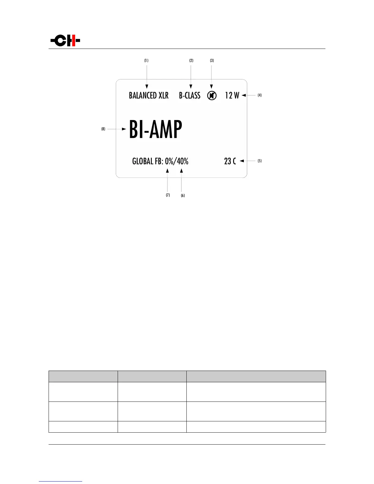
Normal mode display elements
(1) Input connector selected, and impedance termination.
(2) B-CLASS is displayed if the A1 gets too warm and the Class-A polarization is turned off
(3) Mute indication. If the 7 symbol is present, the output is muted
(4) Meter level of instantaneous power. Gives an image of peak power fed to the load. Except for bridged mode, the maximum power (among the 2
channels of the A1) is displayed
(5) Average temperature of the 2 output boards (in degrees Celsius).
(6) Global feedback applied in the right channel output board (only displayed in bi-amp modes)
(7) Global feedback applied in the left channel output board (bi-amp modes) or in both channels output boards (stereo or bridged modes)
(8) Amplifier mode (stereo, mono, bi-amp or bridged)
Displayed elements depend on the installed optional boards and user settings. In the example above, the A1 is set as a bi-
amplifying mono power amplifier, using its balanced XLR input connectors, running in class-B with its output muted (by the way, in
that case the power display should be 0 W). Its internal temperature is 23°C (which is not a temperature at which it can turn to
class-B mode). The left channel is only applying local feedback, while the right channel is applying a mix of 40% global feedback
and 60% local feedback.
Following table shows the actions of the front panel push-buttons in Normal mode.
Front face push buttons Unit State Unit Action
S, short push STANDBY
Any other state
Wake from STANDBY
Mute/Unmute
S, long push STANDBY
Any other state
Wake from STANDBY
Go to STANDBY
N
Any state Enter Shortcuts mode
Rev 2.0 A1 User Manual 25