2.6 Connections
With the two (or four) M10 units placed and levelled, you are now ready to connect your signal cables.
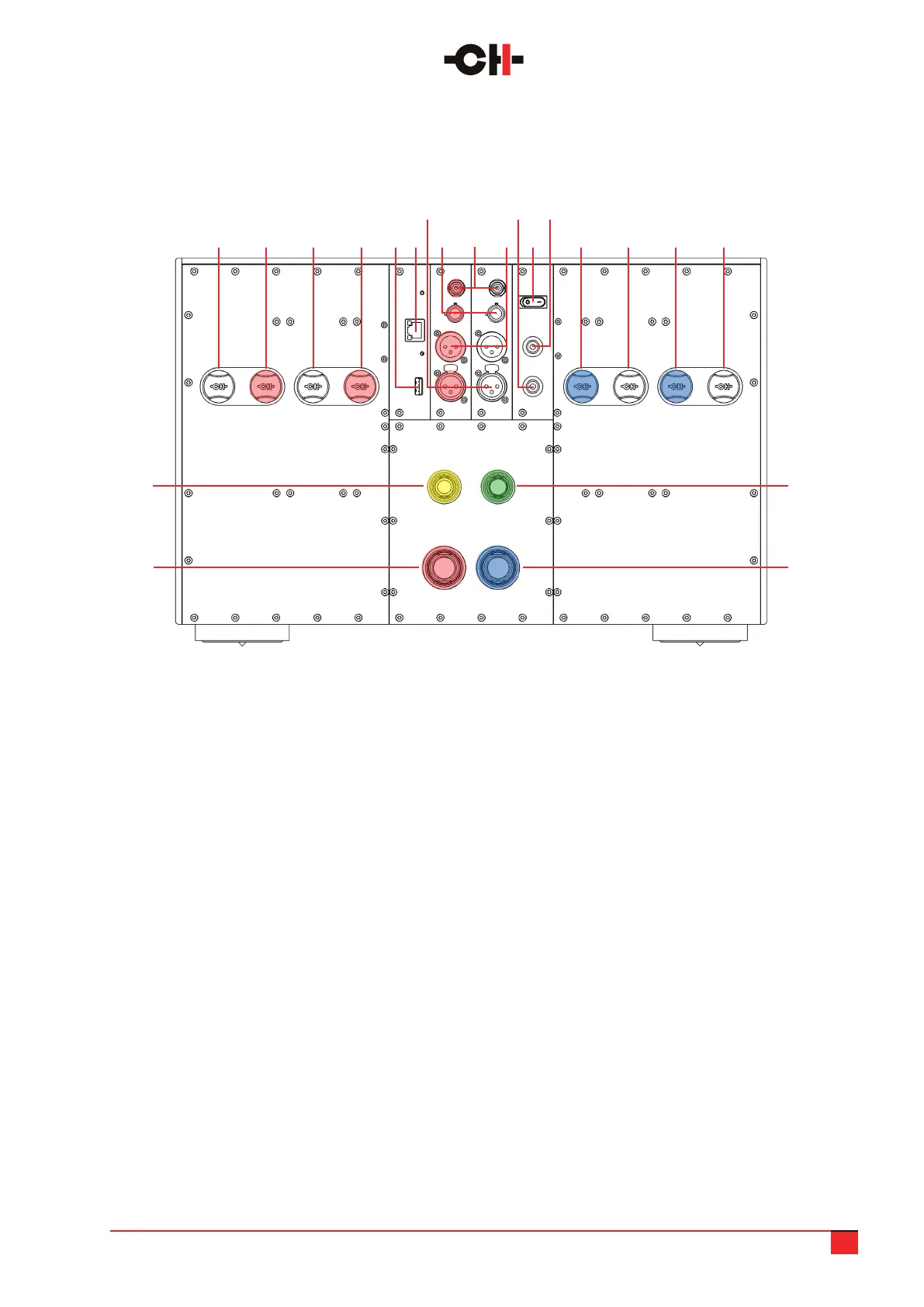
The rear panel layout is shown below:
M10 User Manual 10
1. Right channel negative loudspeaker terminal #2
(customized Argento Audio connector)
2. Right channel positive (or bridged mono positive)
loudspeaker terminal #2 (customized Argento Audio
connector)
3. Right channel negative loudspeaker terminal #1
(customized Argento Audio connector)
4. Right channel positive (or bridged mono positive)
loudspeaker terminal #1 (customized Argento Audio
connector)
5. USB port for software upgrades [CONTROL board]
6. Ethernet port for network remote control
[CONTROL board]
7. Balanced XLR analog inputs (R & L)
8. Single-ended RCA analog inputs (R & L)
9. Single-ended BNC analog inputs (R & L)
10. Balanced XLR analogue outputs (R & L) for
amplier daisy chain connection
11. Earth socket. Internally connected to digital
ground and chassis
12. Ground lift: switch on to connect signal ground
(analog GND) to earth (digital GND)
13. Signal ground (analog GND) socket
14. Left channel positive (or bridged mono negative)
loudspeaker terminal #1 (customized Argento Audio
connector)
15. Left channel negative loudspeaker terminal #1
(customized Argento Audio connector)
16. Left channel positive (or bridged mono negative)
loudspeaker terminal #2 (customized Argento Audio
connector)
17. Left channel negative loudspeaker terminal #2
(customized Argento Audio connector)
18. Analog power supply socket, to be connected
to corresponding cable from power supply unit
19. 2nd high voltage rail socket, to be connected
to corresponding cable from power supply unit
20. 1st high voltage rail socket, to be connected
to corresponding cable from power supply unit
21. Control (digital) power supply socket, to be
connected to corresponding cable from power
supply unit
2 154 171 143 166
7
9
11 13
8 10 125
1821
1920
M10 audio unit rear panel connections