23
INSTALLATION STEP 9
Electrical Requirements
To avoid installation diffi culties, do not run the opener at
this time.
To reduce the risk of electric shock, your garage door opener has
a grounding type plug with a third grounding pin. This plug will
only fi t into a grounding type outlet. If the plug doesn't fi t into
the outlet you have, contact a qualifi ed electrician to install the
proper outlet.
If permanent wiring is required by your local code, refer to the
following procedure.
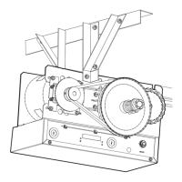
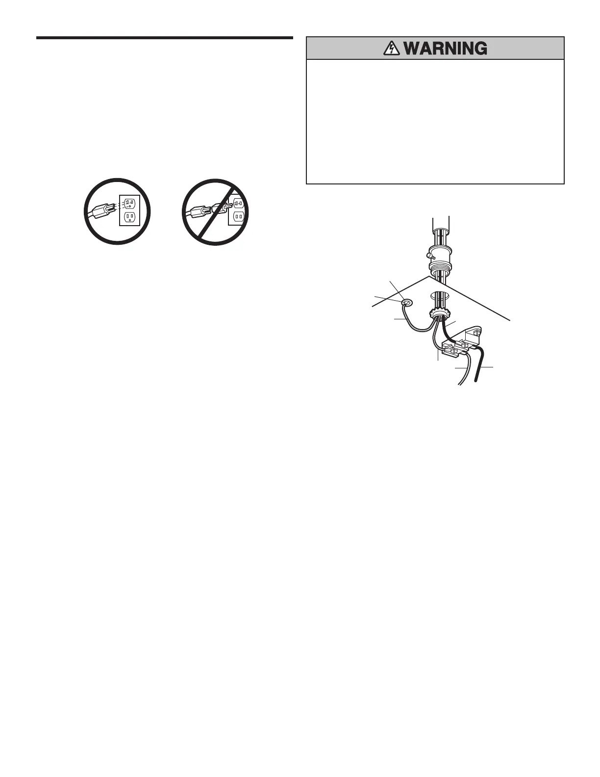
To make a permanent connection through the 22 mm diameter
hole in the top of the motor unit:
• Remove the motor unit cover screws and set the cover aside.
• Remove the attached 3-prong cord.
• Connect the black (line) wire to the screw on the brass terminal;
the white (neutral) wire to the screw on the silver terminal; and
the ground wire to the green ground screw. The opener must
be grounded.
• Reinstall the cover.
To avoid installation diffi culties, do not run the opener at
this time.
To prevent possible SERIOUS INJURY or DEATH from
electrocution or fi re:
• Be sure power is NOT connected to the opener, and
disconnect power to circuit BEFORE removing cover to
establish permanent wiring connection.
• Garage door installation and wiring MUST be in compliance
with ALL local electrical and building codes.
• NEVER use an extension cord, 2-wire adapter, or change
plug in ANY way to make it fi t outlet. Be sure the opener is
grounded.
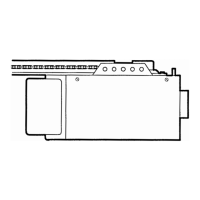
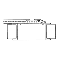
Ground Tab
Green
Ground Screw
Ground Wire
Black Wire
PERMANENT WIRING
CONNECTION
White Wire
Black
Wire