en 6
15 17
18
19
16
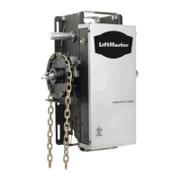
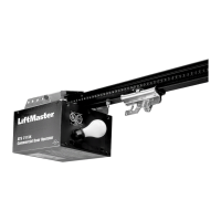
Hang opener Attaching door arm on the trolley
Electrical connection
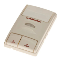
Install illuminated push button or
Multi-function door control (optional accessory)
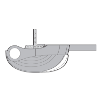
Mounting door bracket
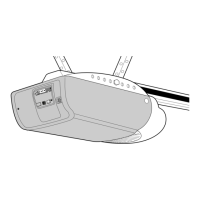
Fully open the door, put down door opener on the door (Fig� A)�
Lay a piece of wood / cardboard on the marked spot (X)�
The opener must be securely fastened to a structural support of the
garage�
Three representative installations are shown (Fig� B)� Yours may be
dierent. Hanging brackets (11) should be angled to provide
rigid support. On nished ceilings, attach support bracket(not delivered)
to a self-supporting structio-nal element before installing the opener� For
concrete ceiling mount, use concrete anchors (22) provided�
On each side of opener measure the distance from the opener to the
structural support (or ceiling)� Cut both pieces of the hanging bracket to
required lengths. Flatten one end of each bracket and bend or twist to t
the fastening angles� Do not bend at the bracket holes� Drill 4,5mm pilot
holes in the structural supports (or ceiling)� Attach brackets to supports
with wood screws (20)�
Lift opener and fasten to hanging brackets with screw (16) and nut (17)�
Check to make sure rail is centered over the door�
Remove piece of wood / cardboard� Operate door manually�
If door hits the rail, raise header bracket�
After the installation of the garage door drive, particularly using a rail
extension, if the rail is observed to be bent up or down for more than 5
cm during the beginning or end of the travel as well as while encounte-
ring an obstacle, a central suspension must be provided by the custo-
mer� For this, please contact the manufacturer of the garage door drive�
NOTE: The attachment point on the door must be the frame or a stable
place on the door panel� If necessary, drill through and screw (not inclu-
ded) together as shown in Fig� B�
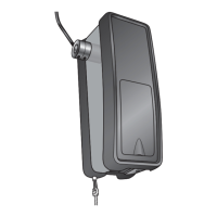
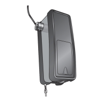
Mount the release handle of the emergency release at at
height of at least 1�80 m� Attach the yellow label regarding
the release of the garage door opener (sticker) on the cord of
the door handle�
The straight door arm is already pre-assembled.
Pulling the red handle the trolley will be released and can be moved
manually�
DISCONNECT THE TROLLEY:
1� The door should be fully closed if possible�
2� Pull down on the emergency release handle�
RECONNECT THE TROLLEY:
The lockout feature prevents the trolley from reconnecting automatically�
Push the green button on the trolley� With the next door movement the
system will reconnect�
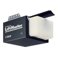
Locate door control where the garage door is visible, away from door
and door hardware and out of the reach of children� Mount at least 1,5
m (5 feet) above the oor. Permanently fasten the caution label perman-
ently to the wall near the door control as a reminder of safe operating
procedures� There are 2 terminals on the back of the door control�
Strip about 6mm of insulation from bell wire� Separate wires enough to
connect the white/red wire to RED terminal screw and the white wire to
WHT terminal screw� Fasten the door control to an inside garage wall
with sheet metal screws provided� Drill 4mm holes and use anchors if
installing into drywall� A convenient place is beside the service door and
out of reach of children� Run the bell wire up the wall and across the
ceiling to the garage door opener� Use insulated staples to secure wire�
Operation of the Door Control:
Press to open or close the door� Press again to stop the door while
moving�
Pay attention to a horizontal course of the rail along the
ceiling�The distance can be adjusted by the given hole spa-
cing. Protruding ends of the ceiling xture can be reduced if
necessary�
In order to avoid personal injury and damage to the device,
the door opener should be operated only if such an inst-
ruction is explicitly stated in this manual� The power plug
must always be accessible for the purpose of disconnecting the mains
supply� Electrical installations may only be undertaken by an authorized
electrician�
Installation in sectional or one-piece doors:
The door bracket (7) has multiple mounting holes� Attach door bracket
top centre on the inside of the door as shown� Mark holes and screw
door bracket�
1� One-piece or sectional door with a guide rail:
distance to door top edge 0-100 mm�
2� Sectional door with two guide rails:
distance to door top edge 100-130 mm�