13
STEP 6
POWER WIRING
This operator can be wired for either 120 Vac or a solar panel (not
provided). Follow the directions according to your application. For
dual gate applications, power will have to be connected to each
operator. Main power supply and control wiring MUST be run in
separate conduits.
The battery is charged in the circuit by the integrated transformer. The
operator requires one 7AH battery (provided) or one 33AH battery. The
33AH application requires the 33AH wire harness (Model K94-37236).
SOLAR APPLICATIONS: For solar applications refer to Solar Panels
section in the Appendix, pages 36-39. Follow the directions according
to your application.
1. Turn off the AC power from the main power source circuit breaker.
2. Run the AC power wires to the operator.
3. Unplug the transformer.
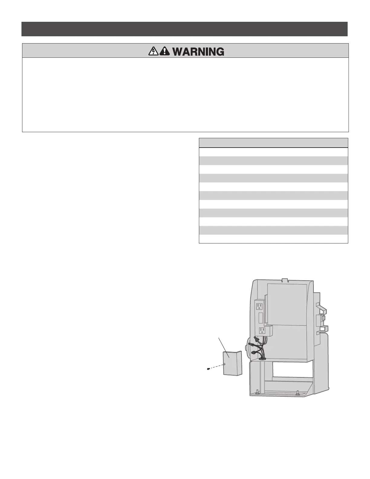
4. Remove the junction box cover.
5. Run the AC power wires through the knockout in the bottom of the
electrical box.
6. Connect the green wire to the earth ground rod and AC ground using
a wire nut. NOTE: The earth ground rod can be grounded to the
chassis.
7. Connect the white wire to NEUTRAL using a wire nut.
8. Connect the black wire to HOT using a wire nut.
9. Replace the junction box cover. Ensure the wires are not pinched.
10. Plug in the transformer.
11. Turn ON AC power to the operator.
NOTE: Use copper conductors ONLY.
Junction Box Cover
INSTALLATION
To reduce the risk of SEVERE INJURY or DEATH:
• ANY maintenance to the operator or in the area near the operator
MUST NOT be performed until disconnecting the electrical power (AC
or solar and battery) and locking-out the power via the operator
power switch. Upon completion of maintenance the area MUST be
cleared and secured, at that time the unit may be returned to service.
• Disconnect power at the fuse box BEFORE proceeding. Operator
MUST be properly grounded and connected in accordance with
national and local electrical codes. NOTE: The operator should be on
a separate fused line of adequate capacity.
• ALL electrical connections MUST be made by a qualified individual.
• DO NOT install ANY wiring or attempt to run the operator without
consulting the wiring diagram. We recommend that you install an
edge sensor BEFORE proceeding with the control station installation.
• ALL power wiring should be on a dedicated circuit and well
protected. The location of the power disconnect should be visible
and clearly labeled.
• ALL power and control wiring MUST be run in separate conduit.
OPERATOR POWER SOURCE
DIRECT PLUG-IN TRANSFORMER (120 VAC)
Wire Gauge 14 1150 feet (351 m)
Wire Gauge 12 1850 feet (564 m)
Wire Gauge 10 2950 feet (899 m)
OR
EXTERNAL PLUG-IN TRANSFORMER (24 VAC)
Wire Gauge 18 150 feet (46 m)
Wire Gauge 16 250 feet (76 m)
Wire Gauge 14 400 feet (122 m)
Wire Gauge 12 600 feet (183 m)
Wire Gauge 10 1,000 feet (305 m)