42
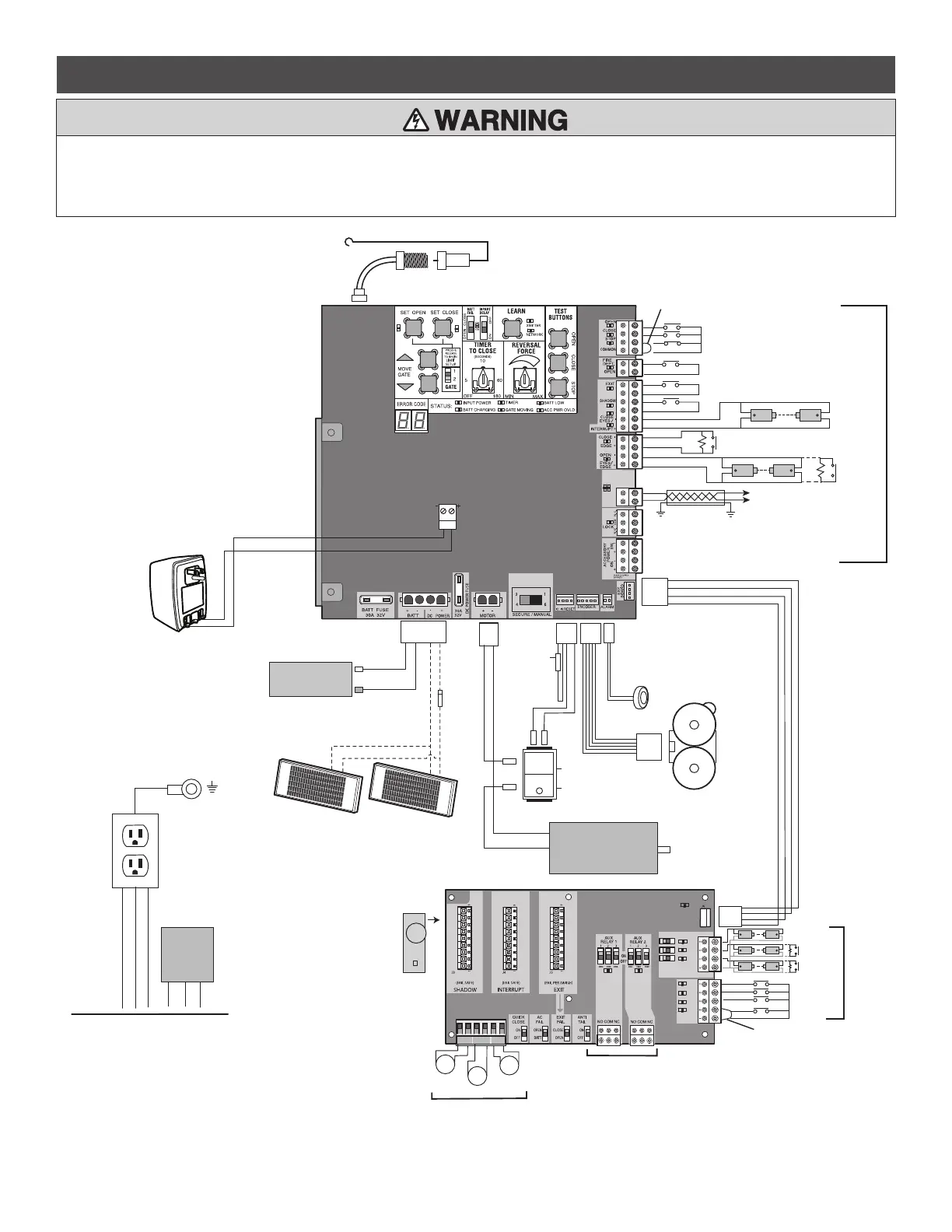
AC & BATT FAIL
BACKDRIVE
COM
LINK
BA
Coaxial Antenna Cable
Accessory Power
Outlets
Antenna
12V 7AH Battery
EXPANSION BOARD
(Optional)
Yellow
Blue
Black
Black
Red
Red
CONTROL BOARD
Piezo Alarm
APS Encoder
1/8 HP 12 Vdc Motor
White
White
Black
Red
Black
Red
Run
Stop/Reset
Reset Switch
To Pin 1
To Pin 2
+
-
+
-
+
+
-
+
-
+
-
+
-
+
-
+
N.C.
Primary/Secondary link
to other gate operator
Shielded
Twisted
Pair Cable
Ground the shield of the
cable to the chassis ground
of each operator.
Photoelectric Sensors
Field Wiring
Edge
Edge
Photoelectric Sensors
Product ID
SHADOW INTERUPT EXIT
SBC
OPN
CLS
STP
COM
EYE
ONLY
EYE/
EDGE
EYE/
EDGE
COM
1
2
3
OPEN
CLOSE
TO MAIN
BOARD
POWER
N.C.
Field Wiring
Field Wiring
EDGE OR EYE
EDGE OR EYE
EYE
Field Wiring
Wire Loop
Wire Loop
Wire Loop
Loop
Detector
Black
Red
Blocking
Diode
WARNING: See Installation Manual
regarding maintenance and required
safety testing prior to servicing.
-
+
+
-
Red
Black
To J25
J25
L
N
GND
N
L
GND
Input Power Connection
Heater
Transformer
One, two, or three 10W Solar Panels wired
in parallel (30W maximum)
Jumper Wire
To Pin 5
To Pin 6
Red
White
Black
Green
Jumper Wire
ANTENNA
ector Diagnostics
LOOPDETLM )
LED EXPLANATION
Normal Operation
nks
or OFF
Open Loop
nks
or OFF
Shorted Loop
nks
ult)
Failed
Authentication
s Successful Reset
nks Loop detector is in
TEST or PROG mode
Active Loop
To protect against fire and electrocution:
• DISCONNECT power and battery BEFORE installing or servicing
operator.
For continued protection against fire:
• Replace ONLY with fuse of same type and rating.
WIRING DIAGRAM