A
32
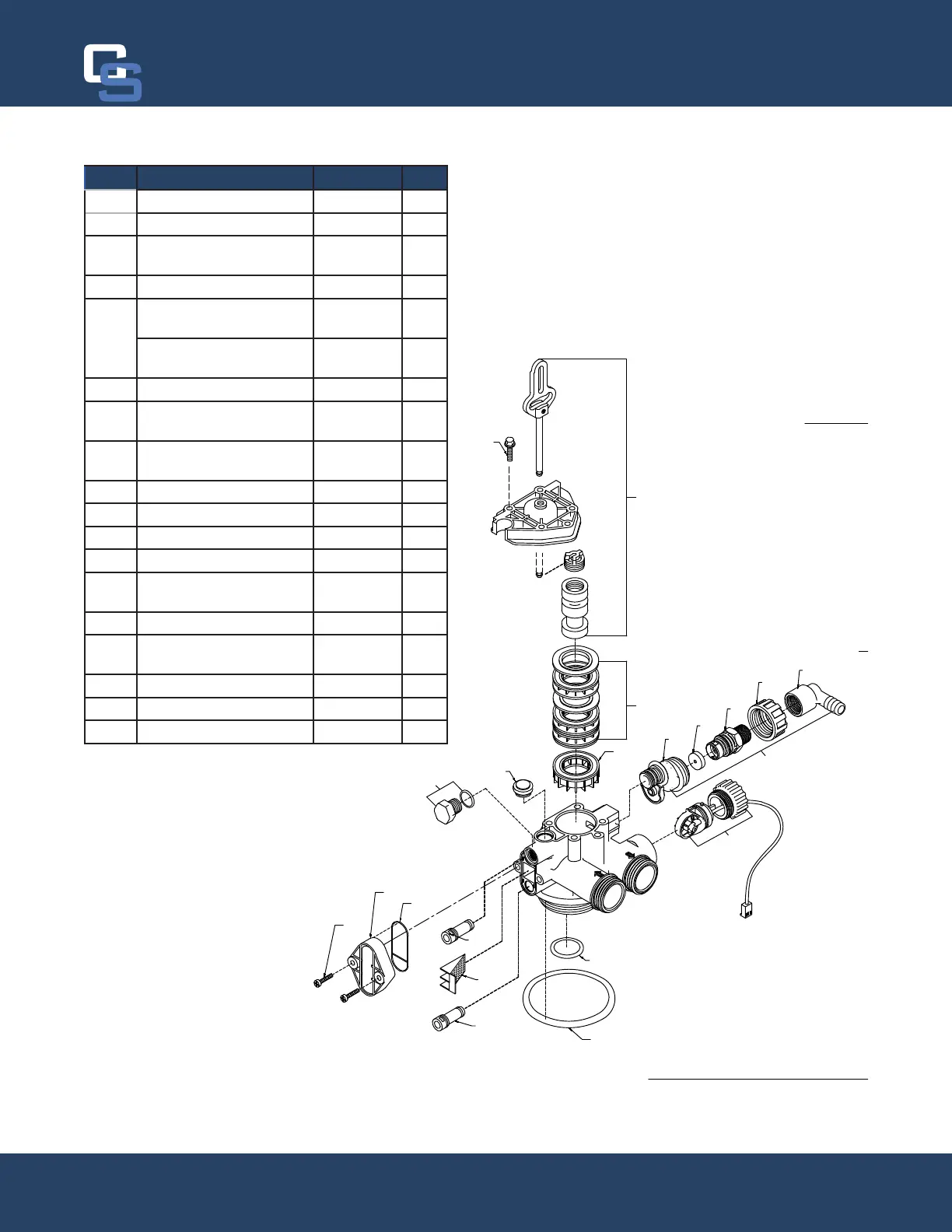
FILTER VALVE
2
8
1
3
11
12
10
16
17
19/20
14
15
4
13
18
9
5
7
6
6
6
6A
REF DESCRIPTION PART NO. QTY
1 Piston Assembly 20001X231 1
2 10-24 X 3/4” Screw SST 20001X001 3
3 Seal and Spacer Kit Incl
(5) #3 & (4) #4
20561X253 1
4 End Spacer 20001X234 1
5 Flow Control Button 5.0
GPM
20251X272 1
Flow Control Button 7.0
GPM
20251X273 1
6A DLFC Assy. 20017X251 1
7 90 Degree Hose Barb
Elbow
20017X266 1
8 Brine Valve Plug w/
O-Ring
20001X230 1
9 Filter Plug Assy. w/ O-Ring 20001X229 1
10 10-24 X 3/4” Screw SST 20001X001 2
11 Injector Cap 20001X223 1
12 Injector Seal 20001X224 1
13 Injector Plug & O-Ring
Assy.
20001X217 1
14 Injector Screen 20001x222 1
15 Injector Plug & O-Ring
Assy.
20001X217 1
16 Valve O-Ring 20015X043 1
17 Dist. O-Ring 20561X204 1
18 Meter Assembly 20017X203 1
Chandler Systems
32