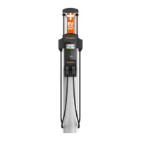
Page 11
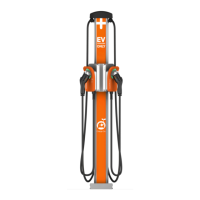
Page 10
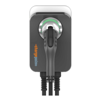
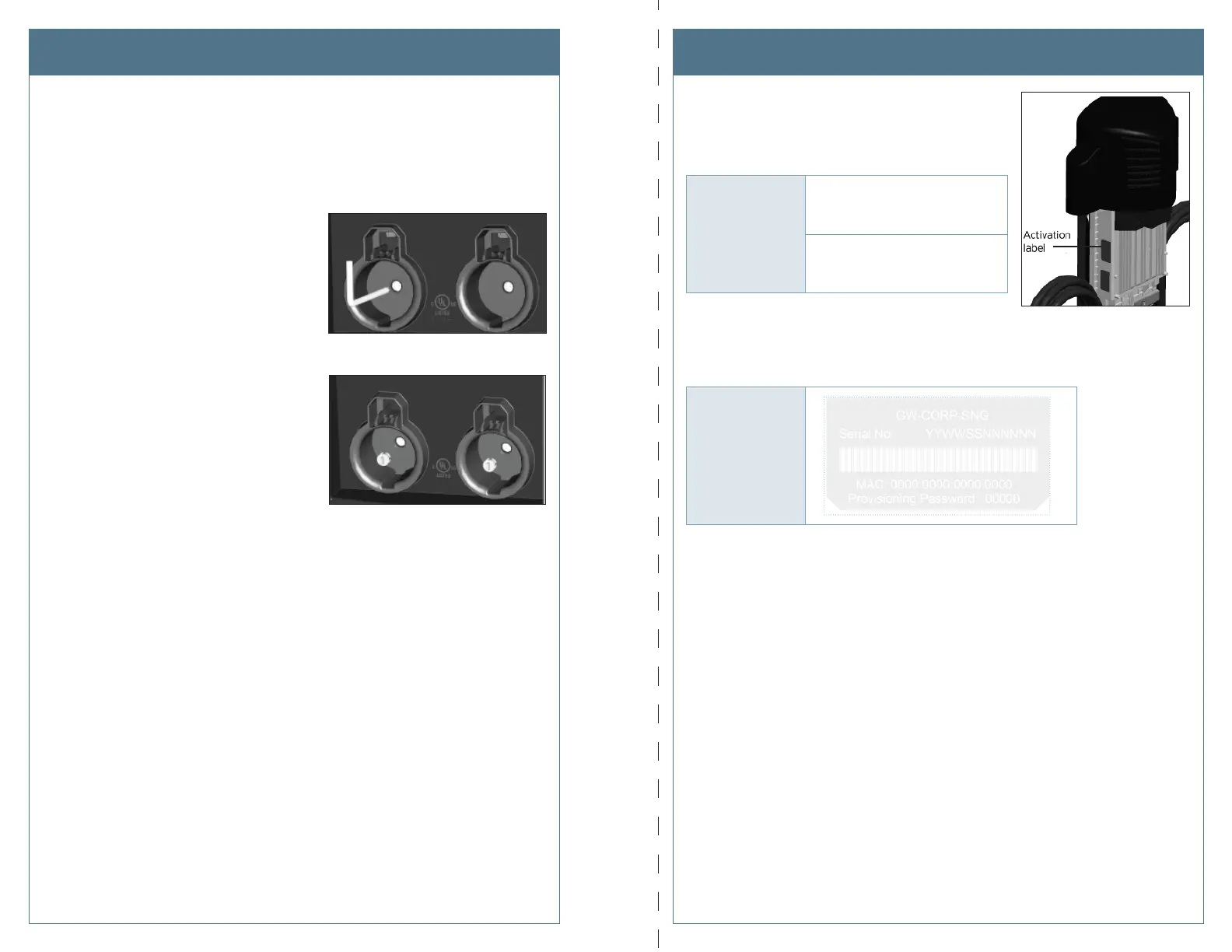
Step 7: Secure the head assembly.
a) Remove the L-wrench from the hole in the right side of the head assembly, then
lower the head assembly. Ensure the head assembly is fully seated and that no gap
exists between the bottom of the head assembly and the main body. The head
assembly fi ts tightly and may require extra downward force to ensure it is fully
seated.
b) Using the T25 L-wrench, tighten the two
security set screws, located inside the
holsters, to approximately 25 to 30 in-lbs.
c) Cover the screws using the two rubber
plugs.
d) Insert the charging plugs into their
corresponding holsters.
You have now fi nished the physical installation of the new head assembly and are ready to
prepare the head assembly for activation on ChargePoint.
Record Station InformationInstall the New Head Assembly
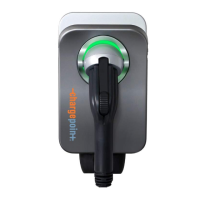
Step 1: Record information from the old head assembly.
Write down the following information from the old head
assembly’s activation label. This label is located on the right
side of the head assembly, as shown.
OLD
Head Assembly
Enter Mac Address here:
__________________________
Enter Activation Password here:
__________________________
Step 2: Record information from the new head assembly.
Place the spare activation label for the new head assembly (included in the shipping box)
here:
NEW
Head Assembly
Step 3: The Head Swap Procedure
After completing the checklist on the following page, tear out this page and provide it to the
person responsible for activating ChargePoint stations. This person will need to perform a
logical head swap to activate the new head assembly on ChargePoint. See Appendix A for
instructions on how to perform a logical head swap.
After completing both sides, cut or tear along dotted line and give it to the person responsible for activating the station.