MANUALPC-2010 CHAPTER IV - OPERATION Page 37
4 - CONDUCTIVITY MENU
Conductivity and TDS
The Conductivity sensor monitors the concentration of Total
Dissolved Solids (TDS) in the water. The conductivity of the
water - in microsiemens per centimeter (µS/cm) - is converted
into ppm or mg/l of TDS with a conversion factor that depends
on the type of ionic species that are present in the water.
Normally, a value of 0.5 is used for water solutions containing
different species of carbonate and chloride ions (see 4.8).
Conductivity or TDS can be controlled in two different
directions:
- downward (decrease) to bleed water when the TDS level
gets too high, or
- upward (increase) to add a salt brine solution for an
electrolytic generator when the TDS level gets too low.
IMPORTANT NOTE: Conductivity control is available only
when Probe Clean control is OFF. It activates the relay
labeled "Acid Clean" located on the Power board.
Conductivity or TDS Displays
Depending on the application, it may be customary to control
either conductivity or TDS. The display is therefore available in
the two systems, as shown on the sample screens.
To change the displays from conductivity to TDS, one simply
enters a TDS factor different from 1 in Submenu (see 4.8 and
4.8.2). If the TDS Factor is 1, the display shows Conductivity
in µS/cm. If different from 1, it shows TDS in ppm or mg/l.
The CONDUCTIVITY or TDS Main Menu screens are similar to
the ones used for other functions, except for the extra line for
SELECT SCALE.
4.1- Control Mode
Line 1 shows the Control mode that is currently selected: OFF,
Manual, AUTO or Timer. To change the Control Mode, select
the first line with the UP or DOWN ARROW keys and press the
RIGHT ARROW key. The Control Mode screen is then
displayed.
The Control Mode screen and selection procedures are
common to all control functions. See CONTROL Submenus,
page 47.
4.2 - Display and Calibration
Line 2 displays the current reading of conductivity in µS/cm or
TDS in ppm or mg/l. The conductivity or TDS readings are
best calibrated with standard calibrated test solutions. If
needed, the CALIBRATION value may be adjusted to allow for
differences or changes in sensor readings.
As with all sensor calibrations, the conductivity sensor can be
calibrated with 1, 2 or 3-Point calibration for origin, slope and
curvature. Press the RIGHT ARROW key to enter the
CALIBRATION Submenu 4.1. The calibration procedure is
common to all control functions. See CALIBRATION details,
page 49.
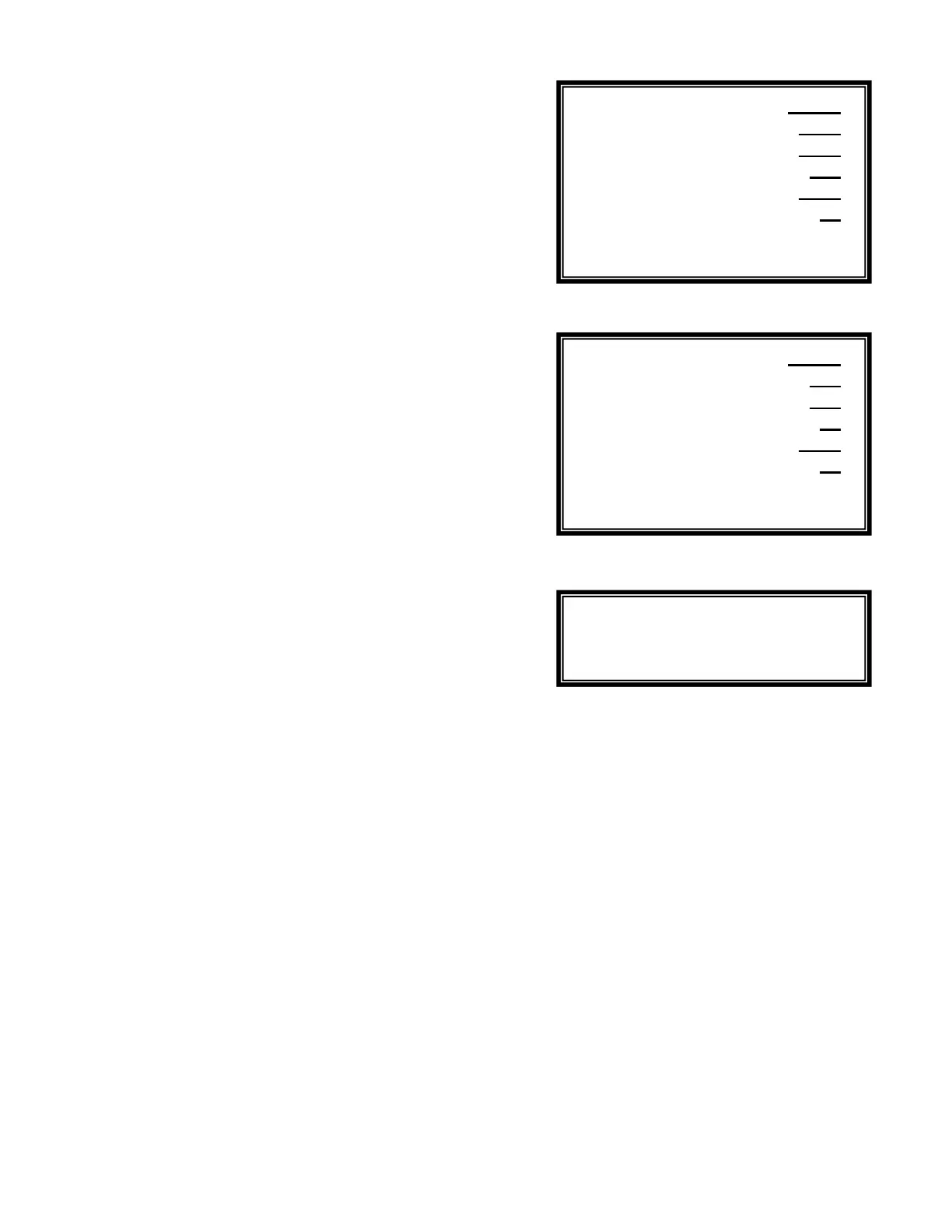
Menu 4
Menu 4 (TDS Alternate)
Menu 4.3.1
4.3 - Setpoint
T
he SETPOINT determines the conductivity or TDS level that
will be maintained automatically by either dumping (bleeding)
water or adding a brine solution - as determined in submenu
4.3.1. To change the setpoint, press the RIGHT ARROW key
and enter the desired value with the digital keypad.
4.4 - Low Alarm
The ALARM LOW value is set to generate an alarm when the
conductivity or TDS reading falls below the set value. After the
alarm value is set, the ALARM OPTIONS screen is shown,
asking whether a low alarm condition should stop the dump
valve and activate the alarm buzzer. There is no particular
danger resulting from a low TDS condition but it may be an
indication of a faulty sensor.
4.5 - High Alarm
The ALARM HIGH value is set to generate an alarm when the
conductivity or TDS reading rises above the set value. After
the alarm value is set, the ALARM OPTIONS screen is shown,
asking whether a high alarm condition should stop the dump
valve and activate the alarm buzzer.
Calibrate uS 1500
Setpoint uS 1500
Alarm Low uS 100
Alarm High uS 3000
Time Limit min 30
Run Time 15 60
Select Scale
Calibrate ppm 750
Setpoint ppm 750
Alarm Low ppm 50
Alarm High ppm 1500
Time Limit min 30
Run Time 15 60
Select Scale
Decrease
Increase
 Loading...