MNL-ISCAN3, REVB INSTALLATION & OPERATION MANUAL Page 14 of 25
DCO #12743 For Technical Support Call: +1.866.821.5504 Schedule Document
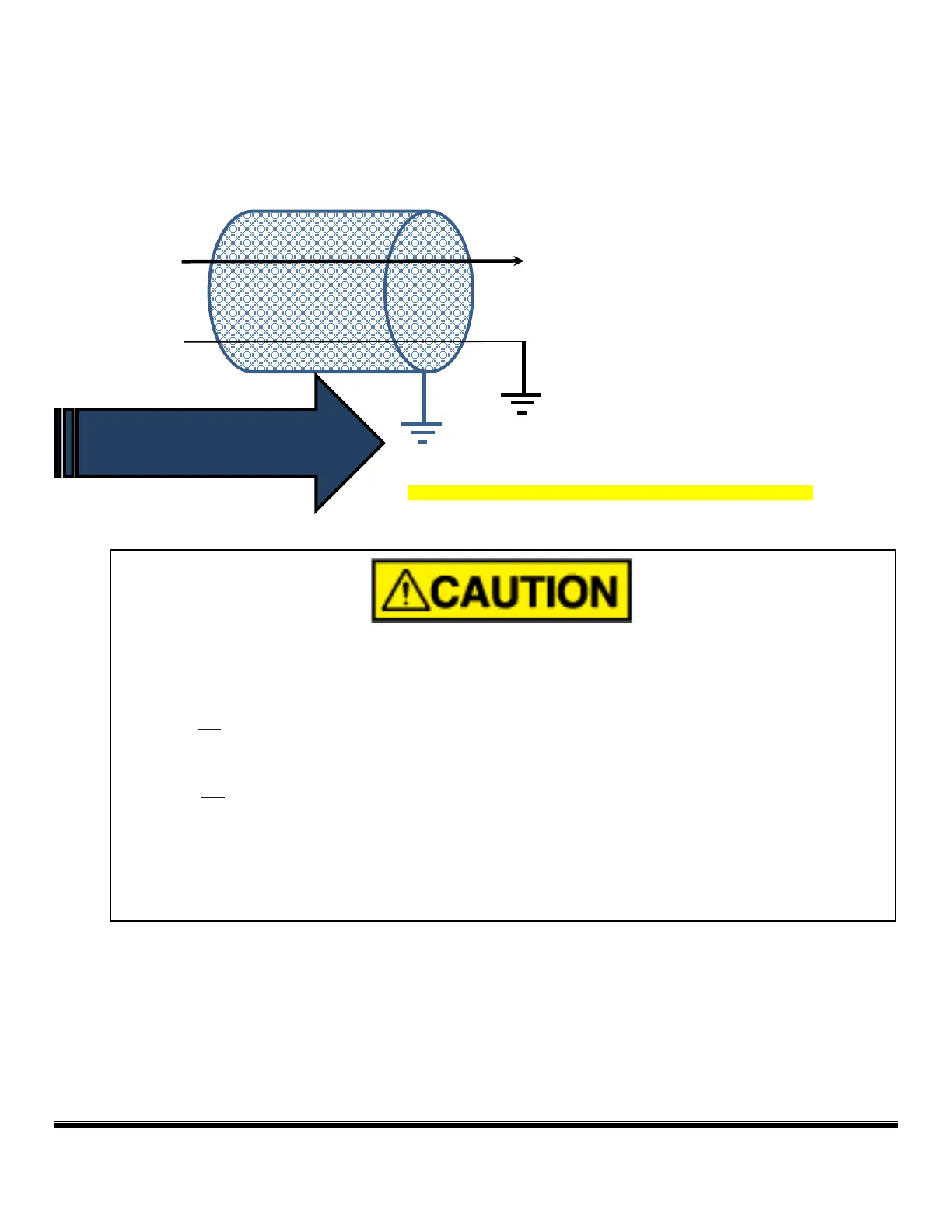
Note 5 Connect the scanner Earth GND (Green/Yellow, 8, <H>) to EARTH GROUND. A short BRAIDED CONDUCTOR
(alternately a short AWG #12 wire) is recommended.
Note 6 All shields are tied to Earth Ground in the Control Panel only.
Electrical noise interference from high voltage/energy ignition sources can adversely affect the operation
of the flame scanner. To minimize the possibility of electrical noise interfering with the operation of the
flame scanner:
• Do not install ignition wires in the same conduit as the scanner wires.
• Ignition Systems shall have a dedicated return.
• Do not mount an ignition transformer in the same enclosure where the flame scanner wiring is
terminated.
• Ignition cables shall be routed a minimum of 12” (305mm) from scanner wiring at all times.
• iScan3 complies with IEC 61000-4-3 (RF Radiated Immunity).
GREEN/YELLOW (8) <H> CONNECT TO EARTH
GROUND. (See section on grounding methods)
CONNECT ALL SHIELDS AT ONE END ONLY TO EARTH GROUND.
DO NOT GROUND SHIELDS AT THE LOCAL JUNCTION BOX.
Earth Ground
Located at CONTROL PANEL