MNL-ISCAN3, REVB INSTALLATION & OPERATION MANUAL Page 18 of 25
DCO #12743 For Technical Support Call: +1.866.821.5504 Schedule Document
Communications Wiring
RS-485
Communication with the iScan3 is RS-485 via a USB to RS-485 Converter (PN 3425-057-01). RS-485 is a differential multi-drop
network. For iScan3, the network is a half-duplex, 2-wire, echo-off configuration operating at 19200 KBAUD. The maximum
allowable number of nodes on a given section of the network is 32 including the USB to RS-485 converter and any repeaters. If
more than 32 loads are connected (1 USB converter, 1 RS-485 repeater and 30 iScan3s) then an RS-485 repeater is required
between sections to boost the signal. The repeater must be compatible with the EIA-485 standard, must have input to output
DC isolation, must operate on 24VDC over the operating temperature range of -30°C to +70°C and must have agency
approvals sufficient to meet the area classification.
NOTE: When calculating 32 loads, include the USB to RS-485 converter and the number of repeaters in a section).
For the extended sections, up to 30 iScan3s may be connected. The maximum length of any given section is 4000 FT
(1200 M).
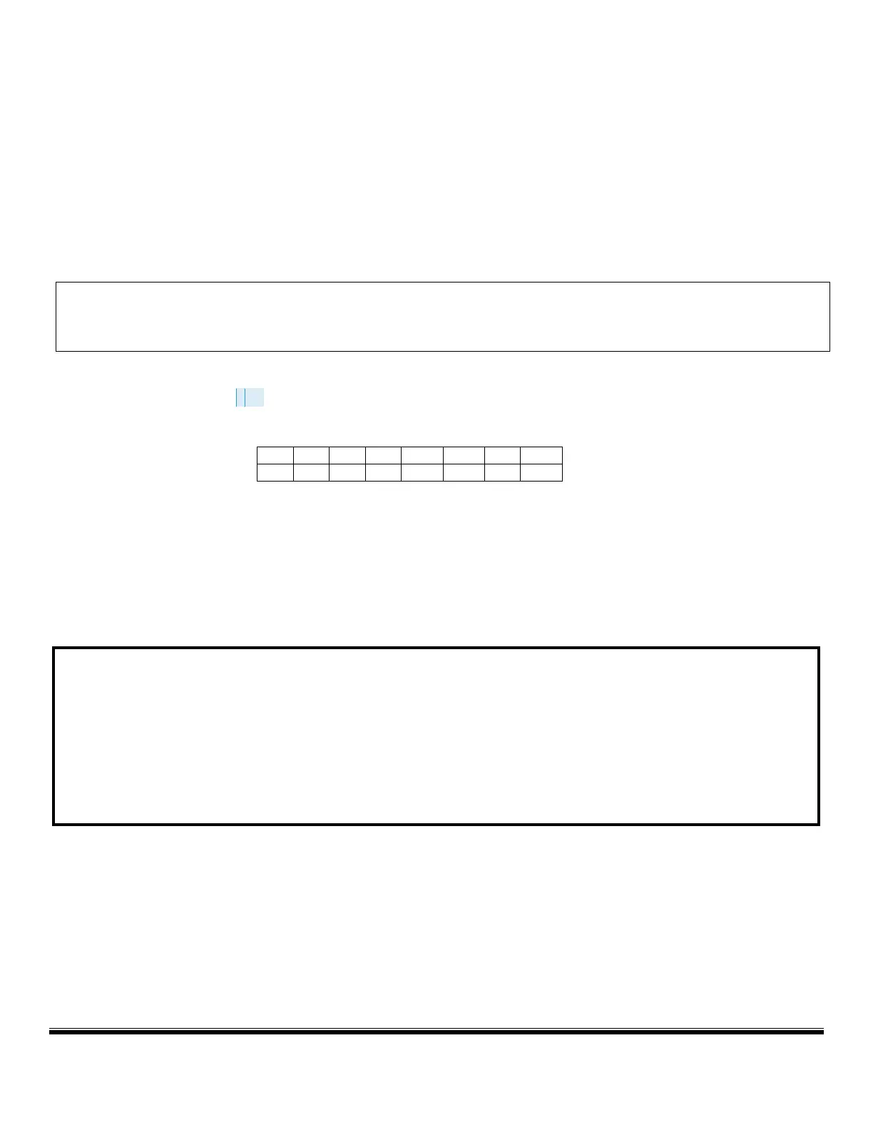
B&B Electronics 485 repeater model 485OPDRI-PH meets these requirements. Additional repeaters may be added to extend
the network to 127 scanners. If
using the B&B Electronics 485 repeater model mentioned above, configure the DIP
switches on ports as follows:
Since there is no dedicated signal reference, the 24 VDC return labeled as DC (-) is used. The USB to RS-485 and the Repeaters
must have their GND terminals connected to the DC (-) as well. Failure to provide the signal reference may result in
communication errors and potentially damage the iScan3.
The recommended topology is “Daisy Chain” as shown in the wiring diagrams below. A split or Y configuration is acceptable.
NO OTHER CONFIGURATION IS ACCEPTABLE. Please refer to the EIA-485 specification for further information on RS-485
networks.
COMMUNICATION WIRING SUMMARY:
• Wiring must be twisted pair shielded cable. Ground the shield only at the control panel to prevent ground loops.
• Use only “Daisy Chain” or “Y” configurations. Connect all of the “Com A” wires together. Connect all of the “Com B” wires together. Make sure that the
“Com A” and “Com B” wires are connected to the correct terminals on the converter.
• An RS-485 repeater is required for every 30 scanners or 4000 ft (1200 m) of length for a maximum of 127 scanners in a network.
• Ensure the DC (-) of all scanners are tied together as a reference for RS-485 communications. The GND terminal of the USB to RS-485 converter and the
repeaters must also be connected to the DC (-) of the scanners.