MNL-ISCAN3, REVB INSTALLATION & OPERATION MANUAL Page 16 of 25
DCO #12743 For Technical Support Call: +1.866.821.5504 Schedule Document
Cable Connection
Power/Control Cable Installation
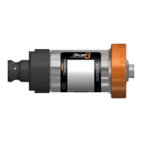
The iScan3 system utilizes a quick disconnect connector to connect the power/control cable to the electronics.
To connect the power cable to the electronics, first turn the locking nut clockwise by hand until it is seated against the
electronics. This will ensure the locking nut is not too far out and will allow the connector to properly seat. Then, align the
connector on the cable with the connector on the electronics, insert the connector, and turn the outer barrel clockwise until
the banjo fittings on the connector are seated and latched.
FIGURE A : CLEAR THE LOCKING NUT THEN ALIGN AND INSERT THE CABLE CONNECTOR.
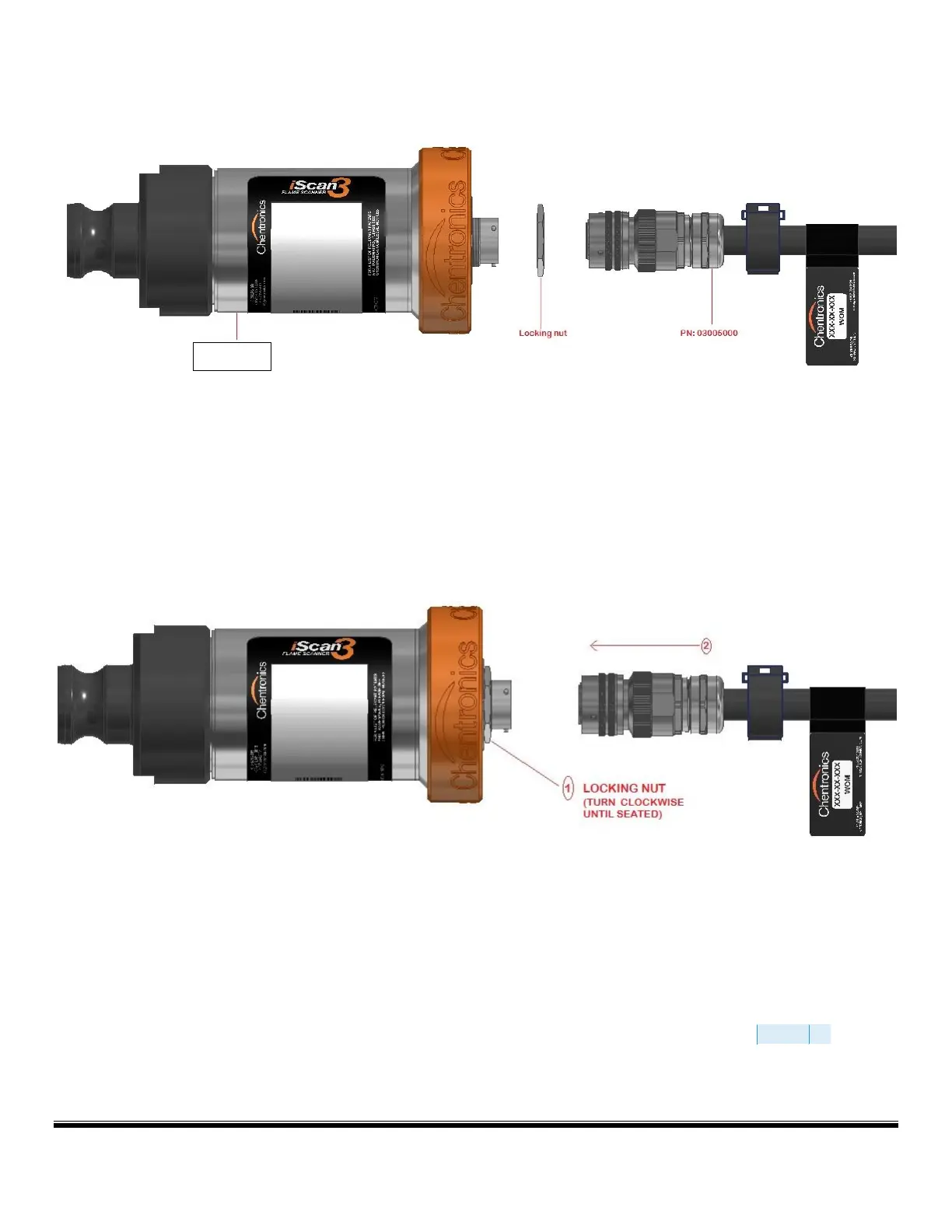
Locking Nut Installation
The equipment features a locking nut that locks the cable to the equipment so that it may not be removed without the use of
a tool. This feature is required for some hazardous area installations. To lock the connector in place, turn the locking nut
counter-clockwise tighten to a torque of 10ftlbs using a wrench. See Figure B and Figure C for illustration of locking nut
tightening.To remove the cable, turn the locking nut clockwise until it is seated against the electronics, then remove the cable
connector by turning the outer barrel counter clockwise until the banjo fittings unseat and the connector unseatS