MNL-ISCAN3, REVB INSTALLATION & OPERATION MANUAL Page 13 of 25
DCO #12743 For Technical Support Call: +1.866.821.5504 Schedule Document
Wiring Instructions
All wiring shall be done in accordance with all applicable local and national codes, standards, and ordinances. The
scanner has a quick connect cable. This cable does not require a flexible conduit if permitted by local authority.
Connections for power, Earth Ground, and Flame Relay (N.O. and Common) are required for all applications. Use of
the 4-20 mA outputs, Communications, and connections are “as-required” for each application.
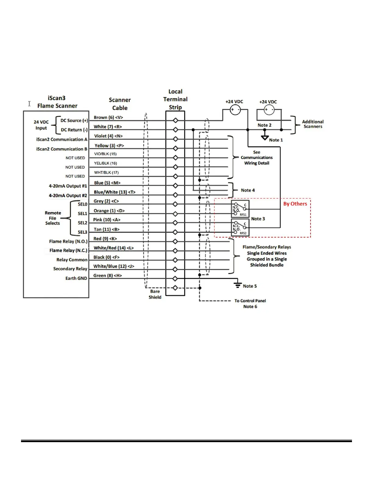
Wiring Diagram
Wiring Notes
Note 1 If more than one 24 VDC supply is required, the 24 VDC returns labeled as “DC (-)” shall be connected to each
other.
Note 2 If more than one 24 VDC supply is required, the 24 VDC source connections labeled as “DC (+)” shall be
isolated from all other power supplies. If switching power supplies are used the supplies may be connected via a
wired OR diode configuration. NOTE: the BLOCKING DIODE must be rated for a minimum of 50 volts and 10 Amps.
Note 3 The 24 VDC return, “DC (-)”, shall be used as the low side of the File Select relays.
Note 4 The 24 VDC return, “DC (-)”, is the return for the 4–20 mA output loop(s). Input must be isolated type.
Maximum current loop resistance is 750 ohms.