Note:
Default factory setting is laser emulation.
Up to two scanner units may be
connected at any one time. In addition to
scanners supplied by Cherry, the
keyboards are also plug-compatible with
many other barcode readers. When
connecting barcode readers – in
particular laser guns – ensure compliance
with manufacturers’ safety guidelines.
Barcode readers should not draw more
than 150 mA of current.
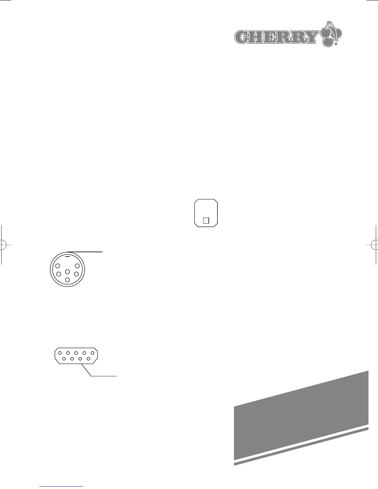
The following diagrams show the
barcode connector pin assignments:
6-POL. DIN 240° SOCKET
1 +5V
2 Video In 2
3 GND
4 Enable Out 2
5 Trigger In 2
6 NC (Good
Read Out 2)
Shield GND
9-pol. SUB-D CONNECTOR S7a
male 1 NC
2 Video In 1
3 Good Read
Out 1
4 +5V
5 Trigger In 1
6 Enable Out 1
7 GND
8 GND
9 +5V
(Front view) Shield GND
When connecting a barcode reading
device, please proceed as follows:
➭ Switch the computer off
➭ Plug the connector of the barcode
reading device into the provided
socket on the righthand side of the
keyboard housing.
➭ Switch the computer back on.
7. Using the integrated
smart card terminals
7.1 Inserting the smartcard
A symbol on the housing indicates which
way round to insert the smartcard:
Vertical smartcard slot:
Insert the smartcard with the chip
underneath, pointing towards the user.
Horizontal smartcard slot:
Insert the smartcard with the chip
uppermost and on the left.
To ensure that the smartcard makes
proper contact with the terminal, insert it
by exerting steady pressure until it snaps
into position.
27
1
2
3
1
6
5
9
4
5
6
SHELL
SHELL
 Loading...