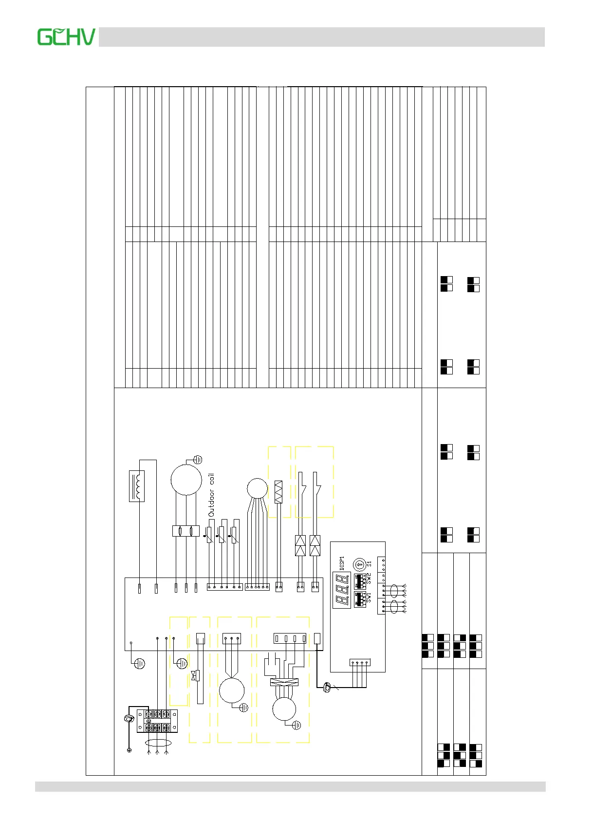
5. Wiring Diagrams
CN25
CN3
P
E
Q
X E Y
C
R YW
G
CN5
4
Failure and Protection
E2
E6
EA
E9
E10
H0
H4
H5
H6
H10
P3
P4
Frequency conversion overcurrent protection
P5
P6
E1
Phase sequence failure
0
2
3
4
5
6
7
8
9
16
18
19
20
21
22
23
24
25
Outdoor after correction demand
26
10
12
13
17
27
14
15
Electronic expansion valve opening
28
29
30
Priority mode: 0:automatic selection; 1:Heating mode is preferred;
- - -
S1 Description
2 Outdoor units type:10KW
3
Outdoor units type:11.2KW
4
Outdoor units type:12KW
5
Outdoor units type:14KW
6
Outdoor units type:16KW
SW2 Description (NO.1 & NO.2 & NO.3)
ON
1
2
3
Automatically select mode is preferred
ON
1
2
3
ON
1
2
3
Refrigeration mode is preferred
Heating mode is preferred
MOTOR
CN20
4-WAY
N
CN1(PFC2)
CN2(PFC1)
COMP1(U)
COMP2(V)
COMP3(W)
CN19
CN13
HEATY
CN5
P1(GND)
CN4(L)
CN3(N)
DC
CN21
VAL
CN10
Outdoor controller
Comp.
Inductor
EXV
U
P2(GND)
power supply
L
N
BL
BR
H
L
BL
BR
BK
CN23
HP
C
P7
P6
P5
T3
RD
(For DC motor
type only)
BL
BL
RD
ELECTRICAL WIRING DIAGRAM
E4
E8
Eb
EC
EE
H7
The decrease in the number of indoor
H9
H11
P1
P2
P9
DC fan protection
P10
Protected against typhoons
P11
Refrigeration T2 high temperature protection
P13
The current detect abnormal protection
L0
DC compressor module fault
L1
DC low voltage protection
L2
DC high voltage protection
L4
MCE fault/synchronous/closed loop
L5
Zero speed protection
L6
L7
Deficiency Protection of Compressor
L8
A moment before and after the speed change
>
15 Hz
L9
Pb
Set speed and the actual speed difference
>
15 Hz
1
11
2:Refrigeration mode preferred; 3:Only heating mode; 4:Only refrigeration mode;
1
Outdoor units type:8KW
ON
1
2
3
Only heating mode
ON
1
2
3
ON
1
2
3
VIP+Automatically select mode is preferred
ON
1
2
3
According to the first mode
SW1 Description (NO.1 & NO.2) SW1 Description
(
NO.3 & NO.4)
ON
1
2
ON
1
2
ON
1
2
ON
1
2
Standard silence mode
Nocturnal silence mode
High hydrostatic mode
Strong mute mode
ON
3
4
ON
3
4
ON
3
4
ON
3
4
Nighttime 6/10
Nighttime 8/10
Nighttime 8/12
Nighttime 6/12
To Indoor
To centralized controller
Check Table
NUM
Display content
Frequency, the number of indoor units
Outdoor power
Indoor demand
Run mode (0: shutdown; 2: refrigeration;
Actual operation ability
Fan speed state (0-8)
T2 average temp.
T3 condensing temp.
T4 outdoor ambient temp.
3: heating; 4: forced refrigeration)
TP exhaust temp.
AC current
DC current
AC voltage
DC voltage
The expansion valve of indoor A
Sof version
Memorizer version
Last failure or protection code
The rest
Comm. failure between indoor and outdoor units
Environment temperature sensor failure
Condensate temperature sensor failure
AC overvoltage/undervoltage protection
EEPROM failure
The protection of three times P6 in 30 minutes
High pressure protection
Low pressure protection
Excessive exhaust temperature protection
IPM modules protection
Comm. failure between master chip and DSP
The protection of three times P2 in 30 minutes
The protection of three times P4 in 100 minutes
TP temperature sensor failure
Reserved
Reserved
Reserved
The number of indoor units
Reserved
Display content
NUM
Code
Code
Failure or protection definition
Failure or protection definition
Reserved
Reserved
Reserved
Reserved
The protection of two times P9 in 10 minutes
The protection of three times P3 in 60 minutes
The protection of two times P13 in 10 minutes
Reserved
Only refrigeration mode
Exhaust temp.
temp.
Outdoor ambient temp.
Crankcase heater
Outdoor Display
Board
T4
TP
W
V
RD
RD
WH
BL
CN24
LP
HP
LP
CN6 CN2CN1
YE/GN
YE/GN
OR
MOTOR
AC
YE/GN
Reserved
Reserved
Reserved
Reserved
Reserved
Reserved
5:VIP+Automatic mode priority; 6:According to the first mode
Frequency limit display: 0:unlimited frequency; 1:T3B frequency limits;
2:T4 frequency limits; 4:T5 frequency limits; 8:Voltage limiting frequency;
16:current limiting frequency; 32:T6 restrictions; 64:mute frequency limit
YE/GN
YE/GN
YE/GN
(For heat pump
type only)
(For AC motor type only)
(For certain
type only)
(For certain
type only)
The wire should be made a
circle around the magnetic loop.
The wire should be made a circle around
the magnetic loop.
(For certain
type only)


 To Next Page