CHV Mini VRF 50/60Hz
201908 77
Part 3 - Installation
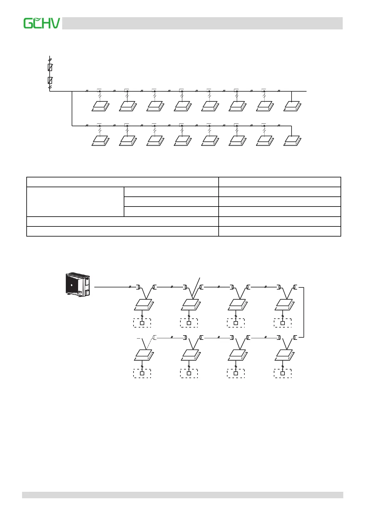
4.2 Indoor unit power supply wiring
Indoor unit
Junction box
Manual switch
Current leakage protection
Indoor power supply
When the power wire is parallel to the signal wire, please put the electrical wires into their own wire pipes, with proper
wire spacing (10A or below: 300mm, 50A or below: 500mm).
4.3 Indoor unit signal wiring
Signal wire ofindoor
and outdoor units
(Open)
Signal wire between indoor units
(1) Please select power source for indoor unit and outdoor unit respectively.
(2) The power supply has specified branch circuit with leakage protector and manual switch.
Indoor unit connect with power supply which is 220-240V~50Hz. Outdoor unit connect with power supply which is 220-
240V~50Hz (Please set all the indoor unit power supply of one system into the same circuit. It should turn on or shut down
the unit at the same time, otherwise, the service life would affect seriously, even the unit may not turn on.)
(3) Please put the connective wire system between indoor unit and outdoor unit with the refrigerant system together.
(4) Use 3-core shielded cable as indoor and outdoor control wire.
(5) Power wiring should be engaged by professional electrician.
Capacity (kW)
2.2-16
Indoor unit power
Phase
Single phase
Frequency and Voltage
220-240V~ 50Hz
Power wiring(mm
2
)
3×1.0
Circuit Breaker (A)
16
Indoor unit/Outdoor unit Signal wire (Weak electric signal) (mm
2
)
3-core shielded wire 3 X0.75
 Loading...