Chiltrix Inc. www.chiltrix.com
Purging Air From DHW Tank & Fan Coils
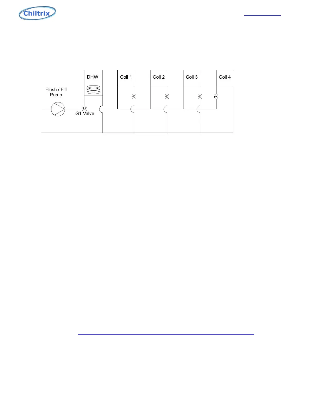
If a DHW tank is installed, it should be the first device on the loop as shown. The G1 valves should
always be as close to the CX34 as possible. The tank should be as close to the G1 valve as possible.
To purge the air from its coil, remove the actuator from the valve body and rotate the valve stub 90°
clockwise to force the water through the coil. Return the valve stub back to its original position
when all of the air is purged. Close the input valve to each fan coil except the first coil (1). Turn the
pump on and run it, when the bubbles stop coming out of the discharge hose turn on the ball valve
on coil (2), wait for the bubbles to stop, then do the same for coil number (3), then (4). All CX
Chillers have a flow switch installed in the loop. Air in the system may cause a flow switch alarm; the
controller will display a P5 error code.
All CXI fan coils have an air purge screw near the water inlet port, always purge the fan coils before
starting the chiller. The CX34 chiller also has a bleeder valve with a ¼” clear tube attached to it
located near the brazed plate heat exchanger.
Fan Coil Flow Balancing (Performed at time of commissioning)
Proper and even flow through each fan coil is important for both heating and cooling. This can be
done with balancing valves or ball valves installed at each fan coil supply or return pipe. This must be
done with the CX34 in heating mode, set loop AC target to the maximum temp setting for
commissioning.
DO NOT DO THIS IN COOLING MODE OR DAMAGE MAY OCCUR.
Adjust valve positions until each fan coil has the same leaving fluid temperature, with all CXIs set to
max manual fan speed and in heating mode. When all leaving fluid temps are the same, the units
are properly balanced. If a fan coil is powered on but the fan isn’t running, there is a good possibility
that there is air trapped in that particular part of the loop. Also verify the parameters with the CXI
FCU manual, page 34. http://www.chiltrix.com/documents/Chiltrix-hydronic-FCU-ver-1.5.pdf
Note – while only one valve per CXI is needed for balancing, best-practice would be to use 2 valves,
one on supply and one on return, so that the fan coil unit could be isolated if needed.
29