043
NVF2G Series Inverter User's Guide
8.2.6 Closed loop PID setting main frequency
Closed loop PID control is a common method of process control. By performing proportional, integral and
differential operations on the difference between the feedback signal of the controlled quantity and the target
signal, the output frequency of the inverter is adjusted to form a closed-loop system to stabilize the controlled
quantity. at target value;
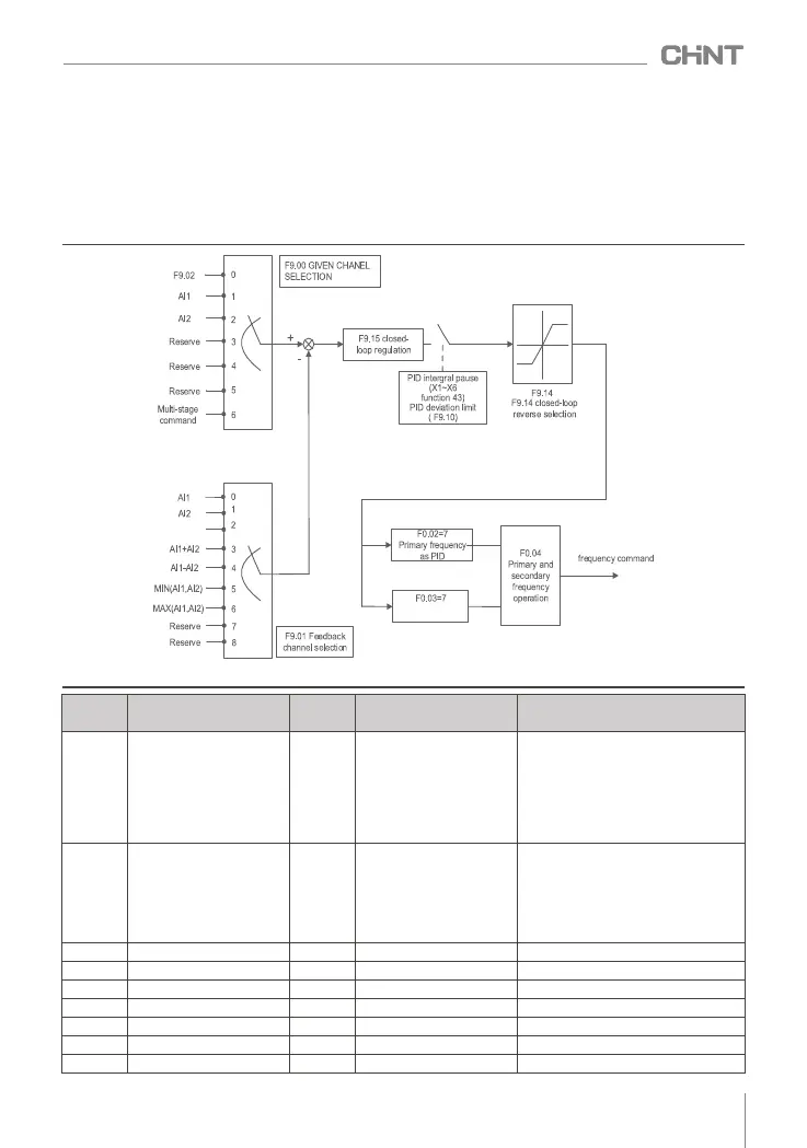
When the system uses closed-loop PID as the command input, if the terminal is set to disable PID (terminal
function 44), the system will switch to the F9.29 standby channel for adjustment.
Figure 8-2-6 Schematic diagram of closed-loop PID as the main frequency
F9.01
Feedback Channel Selection
0 0~6
0 : AI1
1 : AI2
2 : reserved
3 AI1+AI2
4 AI1-AI2
5 MIN(AI1,AI2)
6 MAX(AI1,AI2)
:
:
:
:
F9.02
Given quantity digital setting
50.0%
(0.0~100.0)%
F9.03
Proportional gain Kp
20.0
0.0~100.0
F9.04
Integral gain
2.00
0.01~10.00
F9.05
Differential gain
0.000
0.0000~ 10.000
F9.06
The sampling period
0.50s
(0.01~50.00 )s
F9.07
Given change time
0.00s
(0.00~650.00)s
F9.08
Feedback filter time
0.00s
(0.00~60.00)s
Function
code
Name
Default
value
Predetermined area
Parameter Description
F9.00
Given channel selection
0
0~6
0: digital given
1: AI1
2 : AI2
3 : reserved
4: reserved
5: reserved
6: Multi-stage speed setting
Secondary
frequency as PID
Reser ved



 To Next Page