044
NVF2G Series Inverter User's Guide
F9.09
output filter time
0.00s
(0.00~60.00)s
F9.10
deviation limit
0.0%
(0.0~100.0)%
F9.11
differential clipping
0.10%
(0.0~100.0)%
F9.12
Maximum positive deviation
between two outputs
1.00%
(0.0~100.0)%
F9.13
Maximum reverse deviation
between two outputs
1.00%
(0.0~100.0)%
F9.14
Closed-loop output
reversal selection
0
0 ~1
0: The closed-loop output is negative,
and the inverter runs at the lower
limit frequency
1: The closed-loop output is negative,
and the inverter runs in reverse
F9.15
Closed-loop regulation
characteristics
0
0 ~1
0: positive direction
1: Reverse direction
F9.16
Integral adjustment
characteristics
0
0 ~1
0: stop integration when the frequency
reaches the upper and lower limits
1: When the frequency reaches the
upper and lower limits, continue to
integrate
F9.23
Closed-loop preset initial
value
0.0%
(0.0 ~100.0)%
F9.24
Preset initial value hold
time
0.00s
(0.00 ~650.00)%
F9.25
Given feedback range
1000
0 ~65535
F9.26
Feedback loss detection
value
0.0%
(0.0 ~100.0)%
F9.27
loss detection time
0.0
(0.0 ~20.0)%
F9.28
Closed loop operation
mode
0
0~1
0: no operation when stopped
1: Computing at shutdown
F9.29
Closed Loop Alternate
Channel Selection
0 0~4
0 : digital setting
1 : AI1
2 : AI2
3 : reserved
4 : reserved
Function
code
Name
Default
value
Predetermined area
Parameter Description
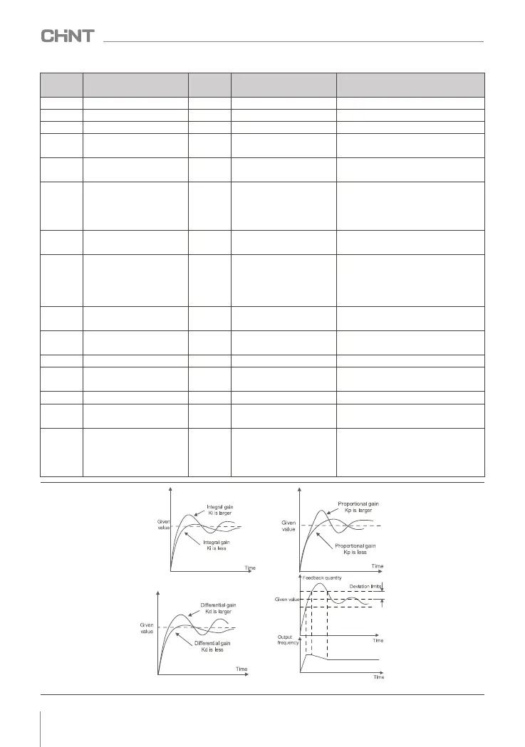
Figure 8-2-7 Influence of Closed loop PID Parameters