NVF5 Series User Manual Appendix A RS485-MODBUS
Communication Instructions
In ASCII mode, the frame head is"0x3A", the default frame tail is“0x0D, 0x0A”, and
the frame tail can be configured by users. In this mode, besides the frame head and tail,
the other data bytes are all sent in ASCII code; upper 4-bit byte is sent first, followed by
lower 4-bit byte. Data in ASCII mode is 7-bit bytes long. For “A”~“F”, their ASCII codes in
capital are used. At this time, the data adopts LRC check, and the check covers the
information from the slave address to data. Checksum is equal to the complement of
sum (carry bits are abandoned) of all characters participating in the data check.
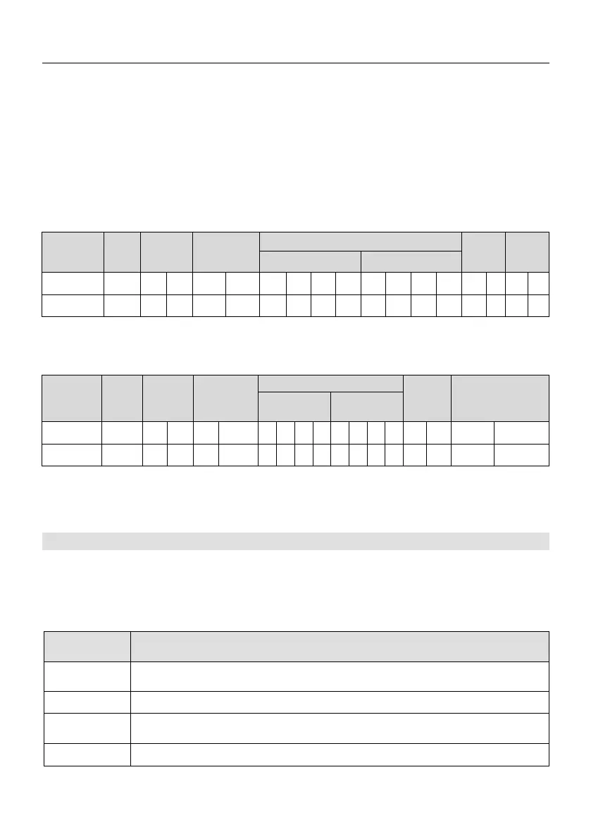
The following examples are used to write 4000 (0xFA0) to the internal register 0201
(A2.01) of slave 5 in ASCII mode.
Request frame:
Head
Slave
Address
Command
Code
Code
Tail
Register Address
Written Content
Character
:
0 5 0 6 0 2 0 1 0 F A 0 4 3
CR
LF
ASCII 3A 30 35 30 36 30 32 30 31 30 46 41 30 34 33
0D
0A
the check code is LRC checksum; its value is equal to the complement of
(05+06+02+01+0x0F+0xA0).
Response frame:
Head
Slave
Address
Code
Check
Code
Frame Tail
Character
:
0 5 0 6 0 2 0 1 0 F A 0 4 3 CR LF
ASCII 3A 30 35 30 36 30
32
30
31
30
46
41
30
34
33 0D 0A
The inverter can set different response delay through the function codes to adapt to
the specific application needs of various master stations. For RTU model, the actual
response delay is not less than 3.5 characters; In ASCII mode, the actual response delay
is not less than 1ms.
A.5 Protocol Application
A.5.1 Modbus Command Code
The main function of Modbus is to read/write the parameters of inverter; different
command codes determine different operation requests. Inverter Modbus protocol
supports the operation in the table below.
Table A.1 ModbusCommand Code and Description
Description
0x03
Read inverter parameters, including function code parameters,
command parameters and status parameters.
0x04
Read inverter parameter attribute value.
0x06
Rewrite single 16-bit bytes inverter function code parameters or
command parameters.
0x10
Rewrite multiple inverter function codes or command parameters.。
A.5.2 Address mapping rule for function parameter of inverter
- 103 -
 Loading...
