NVF5 Series User Manual Chapter 3 Installation and Wiring
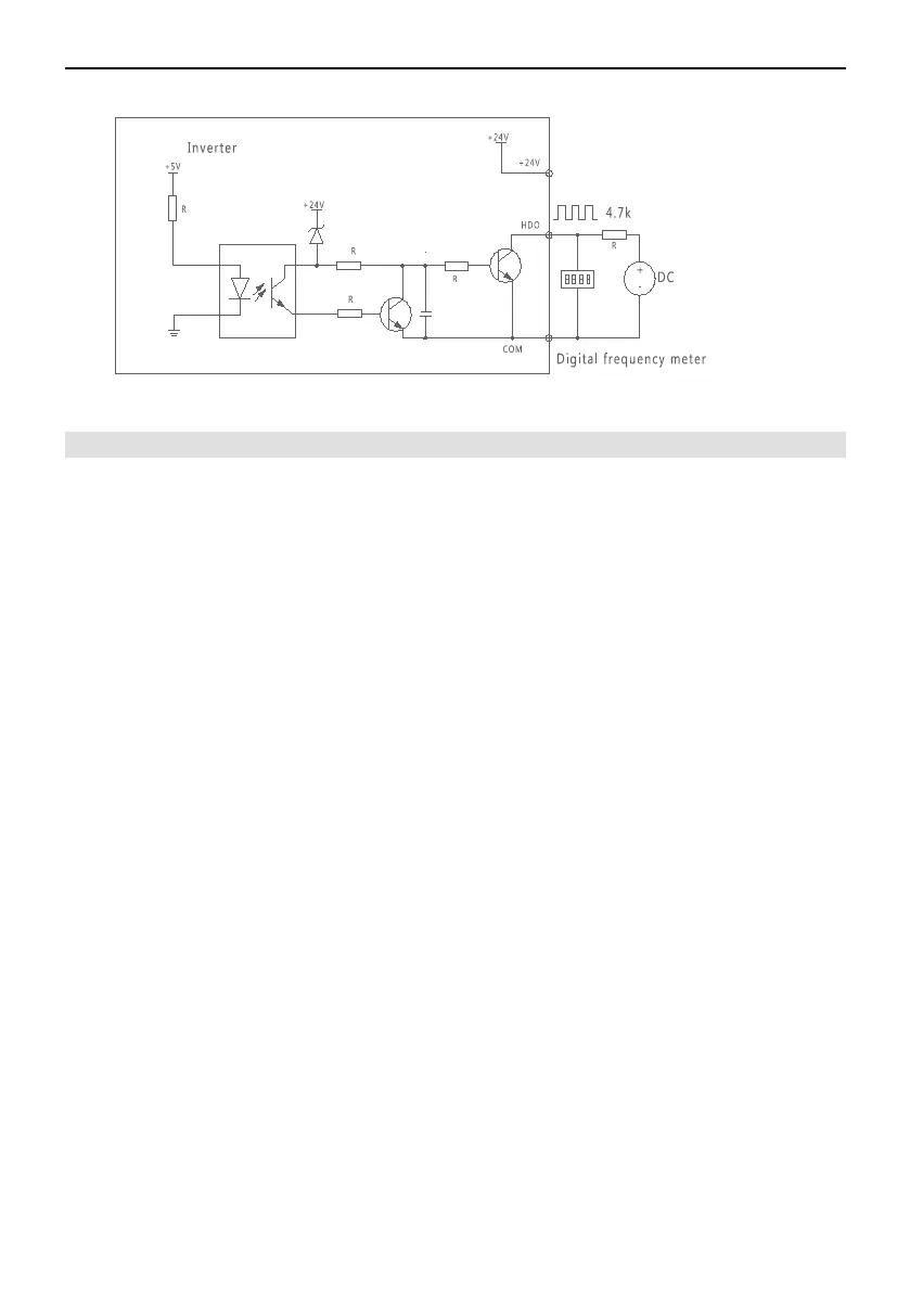
Figure 3-6-4 HDO Connection Mode2
3.7 EMC Precautions
The inverter can produce electromagnetic interference,this interference will affect
automation devices and instruments probably.Correct installation can reduce
electromagnetic nosie of devices and improve the interference resistance . To ensure that
the inverter can run normally for a long time, please refer to the following installation
description.
3.7.1Field Wiring
Equipment classification:When multiple equipment is mounted in a common
enclosure,such as inverter, filter, PLC and detection instrument . According to the
ability in emitting electromagnetic noise externally and bearing noise, the devices are
classified into strong-noise devices and noise-sensitive devices. The same type
equipment shall be installed in the same area. The different type equipment shall be
kept distance of 20cm or above. It is suggested to isolate different areas spatially through
metal shells or grounding partition plates in the enclosure.
Wiring in the enclosure: Main power cables and signal cables are generally
arranged in the enclosure. The signal cables are easy to be interfered by the main power
cables and then cause equipment trip. So, the signal cables and the main power cables
are supposed to be distributed in different areas, not in the same cable tray, it is prohibited
to arrange parallel wiring and alternate wiring of the signal cables and the main power
cables in the close distance of 20cm, and the signal cables and the main power cables
shall not be bound together either. If a signal cable must go across a power cable, a
90-degree angle shall be maintained between the signal cable and the power cable. Input
and output cables of the main power shall not be alternately arranged or bound together.
3.7.2 Noise Suppression and Grounding
The inverter must be grounded reliably in the operating process. Grounding is
conducted for the safety of equipment and people and furthermore provides a simplest
and most effective method with lowest cost for solving EMC problems, thereby deserving
priority in consideration.
Shielding cables shall be adopted for all control terminals of the inverter. The
shielding layer is grounded nearby the inlet of the inverter. Cable clamps are adopted for
- 24 -
 Loading...
