Section 2: Installation and Setup
2-14 013-100199-04
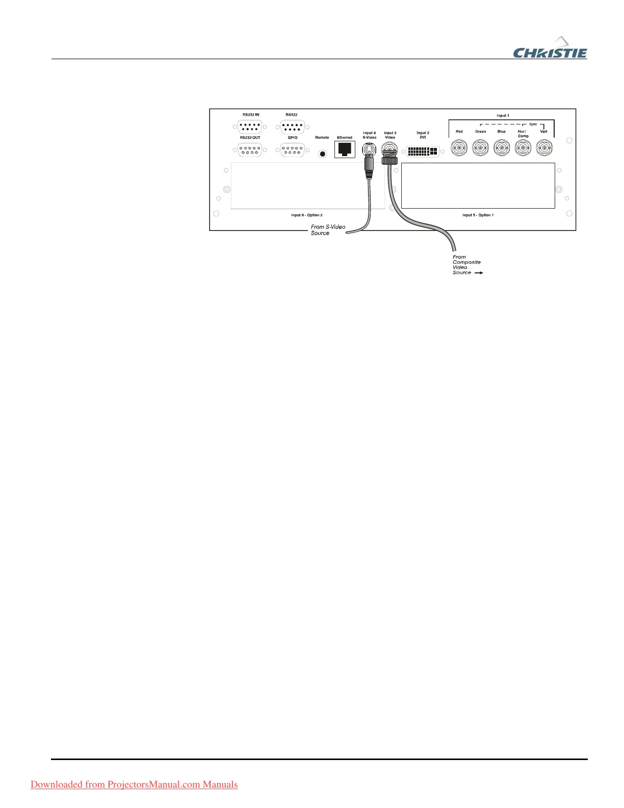
INPUT 3 and INPUT 4 provide simultaneous connection of both a composite video
source (
INPUT 3) and an S-Video source (INPUT 4). See Figure 2.9.
Figure 2.9.Connecting Composite or S-Video sources
Use the DVI-I connector at INPUT 2 to connect either analog or digital video devices
to the projector. When connecting devices that transmit an analog video signal such as
VCRs, laptops, and PCs use the DVI cable provided with the projector. Plug the
DVI-I (single link) connector end to the projector and the 15-pin VGA connector to
the device.
Use a cable with DVI-I connectors at both ends to connect devices that transmit
digital and analog video signals such as high-quality DVD players, satellite receiver
and digital cable TVs.
NOTES: 1) To ensure true digital output from devices that transmit digital signals,
connect to the DVI-I connector. 2) DVI loop through is not available unless you have
the optional DVI Input Module installed at
INPUT 5 or INPUT 6.
Optional modules allow you to increase your total number of inputs and/or
accommodate different signal types, whether analog or digital. Install in the areas
labeled
INPUT 5 or INPUT 6. Options include:
• RGB 500 Input Module
• RGB 400 Active Loop Thru Input Module
• RGB 400 Buffered Amplifier Input Module
• PC250 Analog Input Module
• Serial Digital Input Module
• DVI Input Module
• Dual SD/HD-SDI Module
NOTE: See Appendix F – Optional Input Modules for a brief description of each
interface.
Com
osite and S-Video f
DVI Di
ital Video f
O
tional In
uts f
Downloaded from ProjectorsManual.com Manuals