Wound Component EST Scanner 19035/19035-M/19035-S
Quick Start Guide
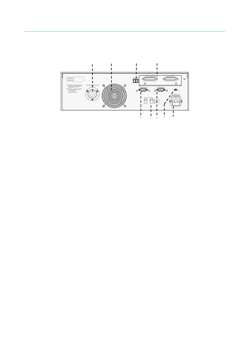
3.2 Rear Panel
9 6
1 5
3
4
7 82
Figure 3-3
1. INTER LOCK: Short-circuit these two terminals can output the high
voltage.
2. VOLTAGE SELECTOR: It changes the Input AC power supply of the
Scanner. Switch the voltage selector and change the fuse based on
the AC power supply.
3. AC LINE: It contains a three-wire AC power socket and a fuse holder.
4. GND: It is the safety grounding terminal. Please use an appropriate
tool to connect it to earth properly.
5. GPIB/HANDLER INTERFACE: (Option)
These two sockets are for the optional GPIB/HANDLER/TC 3 in 1
interface card that can be purchased for this Scanner.
6. FAN: The fan is activated simultaneously when the Scanner is
powered on.
7. RS232 INTERFACE#1: It is the RS232 interface socket that can be
used to connect PC or ECG WindingTester DWX-05/10.
8. RS232 INTERFACE#2
It is the second RS232 interface socket ordered optionally. To use the
RS-232 to connect with the PC and the ECG Winding Tester
DWX-05/10, please use RS-232 INTERFACE#1 to connect the ECG
Winding Tester DWX-05/10 and RS-232 INTERFACE#2 to connect
the PC.
9. IWT INPUT: This terminal is used to connect the output of ECG
Winding Tester DWX-05/10.
13