General Information
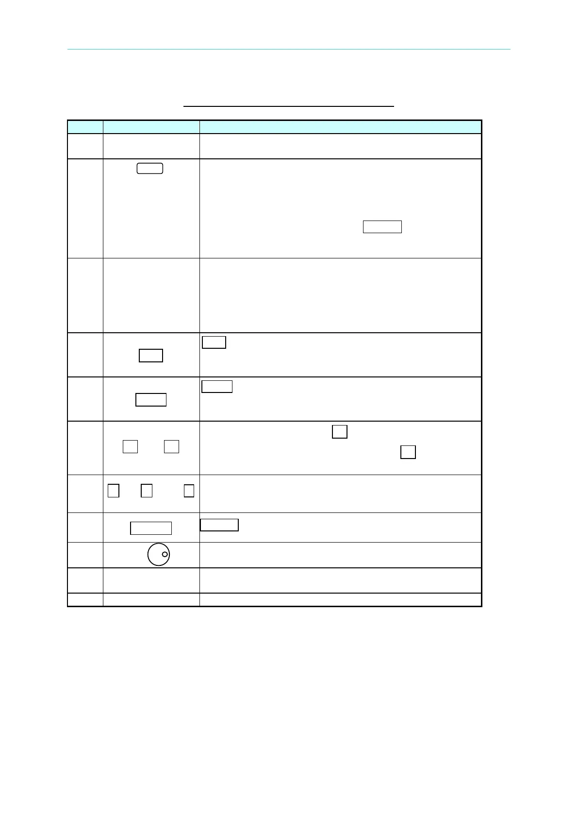
Table 1-1 The Description of the Front Panel
1
Display: The LCD is to display configuration, output setup,
and measurement results.
2
Soft keys: Five soft keys are located at the right side of the
LCD. Each of them gives a command as indicated on the
corresponding command block on the LCD next to the soft
keys to guide the user unless that block is blank. Each
valid soft key denotes the command string lying within the
symbol of a soft key; for example,
CONFIG represents that
the soft key next to command block “CONFIG” is for
entering configuration menu.
3
Cursor moving keys: These four keys are to move the
cursor to different directions respectively. In normal mode
(non-editing mode), pressing any of these four keys will
change the place of the cursor. In editing mode, pressing
or will move the cursor from digit to digit for the
programming of a parameter.
4
A EditE
A EditE A command key: Pressing this key will make the user
enter into or quit from editing mode while he is
5
A LocalE
A LocalE A command key: Pressing this key
control of the AC source from remote operation to
operation through the keypad on the front panel.
6
A ▲E A and A ▼E
Up and down keys: Press A ▲E A to search upward for the
desired programming parameter. Press
▼ to search
7
0 to 9 , and
Numeric and decimal keys: The user can program
numeric data by pressing the digital keys and the decimal
8
ENTER
ENTER key: It is to confirm the setting of parameters.
9
RPG: The user can input programming data or options by
turning the RPG to the desired ones.
10
Airflow inlets: Cool airflow enters the AC source through
these holes.
Main power switch: It is to power on or off.