CIAS Elettronica S.r.l. Ed. 2.2
Installation Handbook page 38 to 43 ERMO 482
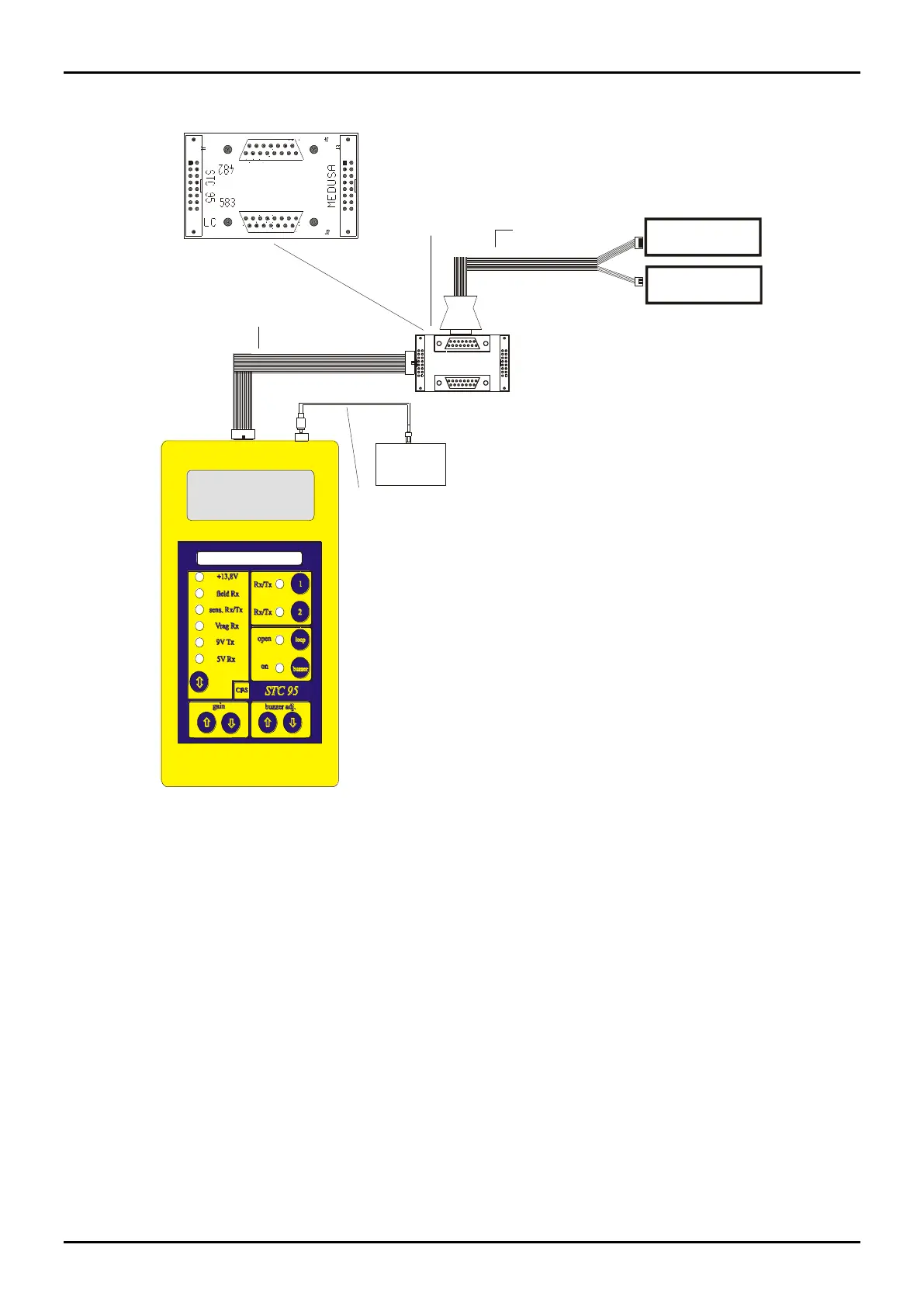
STC 95 connections to ERMO 482 CIAS Barriers
flat STC 95
Flat Cable
ermo 482 / 583
IFB
Module
Connector 7 pin
ermo 482 RX
Connector 4 pin
ermo 482 TX
Oscilloscope
RCA /BNC Cable
Figure 11
4.1.1 Transmitter Setting-up
To align and adjust the Transmitter ERMO 482 proceed as follows:
- unscrew the specific screws to remove the front cover ( Radome );
- activate the power supply connection to MS1 terminal block;
- check that the Main led indicating presence of mains lights up;
- connect the “fastons” to the battery paying attention to the polarity (red lead to battery positive,
black lead to battery negative);
- preset one of the 4 channels available through the channel selector DS1 (figure 8).