CIAS Elettronica S.r.l. Ed. 1.5
Installation Handbook Page 40 of 57 MANTA 50 – 80
3 CONNECTIONS
3.1 Terminal Blocks, Connectors and Circuit Functions
3.1.1 Transmitter Circuit
1
TMP
TMP
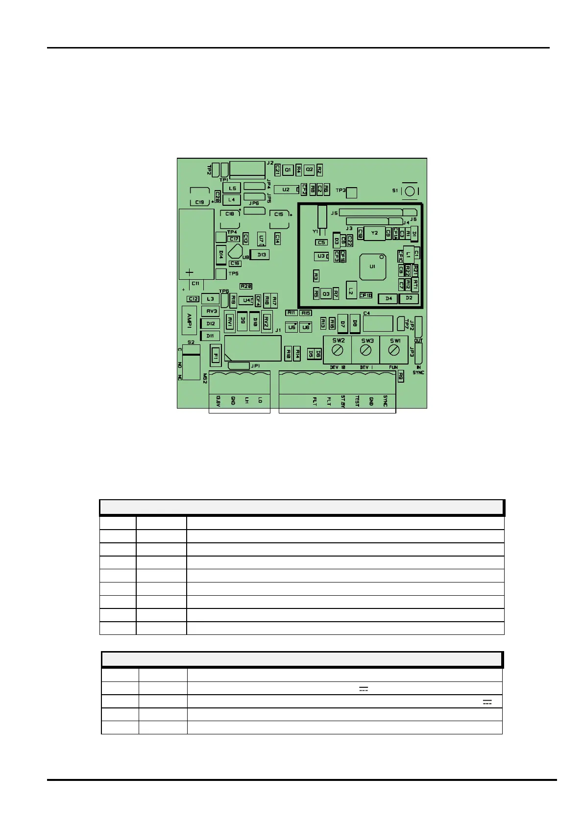
Figure 8
Layout of connectors, jumpers, LEDs and presetting in transmitter board
The following tables shows the connector pin functions present on MANTA Transmitter
Tamper relay contact (Normally Closed) + bulb contact (AMP1)
PT 2 Tamper relay contact (Normally Closed) + bulb contact (AMP1)
Fault relay contact (Normally Closed)
Fault relay contact (Normally Closed)
ST BY Auxiliary input for Stand-By command (Norm. Open from GND)
Auxiliary input for Test command (Norm. Open from GND)
Ground auxiliary connection
SYNC Sync In/Out connection to perform Slave/Master operation
TRANSMITTER TERMINAL BLOCK MS
+13,8 Positive Dc Power Supply (+13,8 V )
Ground connection for Data
LO - RS 485 (Low Data Line)