CIAS Elettronica S.r.l. Ed. 1.5
Installation Handbook Page 41 of 57 MANTA 50 – 80
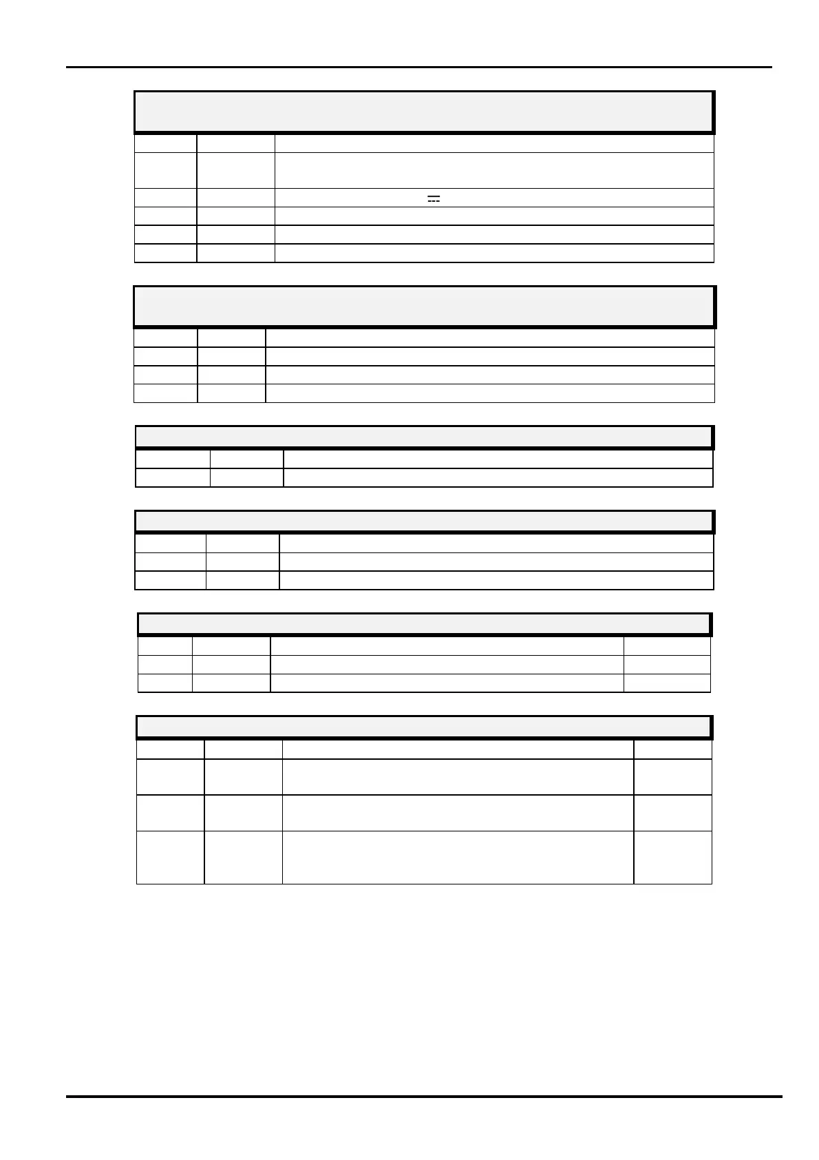
TRANSMITTER CONNECTOR J1
PC Serial Line connection
1-2-4-
N.C.
Not Connected
+13,8 Power Supply (13,8 V )
GND
Ground
TRANSMITTER CONNECTOR J2
Connector for MW oscillator (DRO)
GND Ground connection for MW oscillator
Modulation Frequency connection for MW oscillator
Ground connection for MW oscillator
TRANSMITTER CHANNELS SWITCH
FUN Hexadecimal Modulation Channel Selector
RANSMITTER NUMBER OF BARRIER SWITCHES SW2 SW3
DEV 10 Barrier Number selector (tens column)
DEV 1 Barrier Number selector (units column)
N°
Symbol Function
Default
1
Jp1 RS485 Line termination (Jp1 position 1/2 = line
1/2
2
Jp2 Enable for FW download (Jp2 position 1/2 = FW
download NOT enabled)
1/2
3
Jp3 Internal Modulation signal (Tx-Master, Sync-Out
Jp3 = position 2/3) or External Modulation signal
OUT
2/3