CIAS Elettronica S.r.l. Ed. 1.5
Installation Handbook Page 42 of 57 MANTA 50 – 80
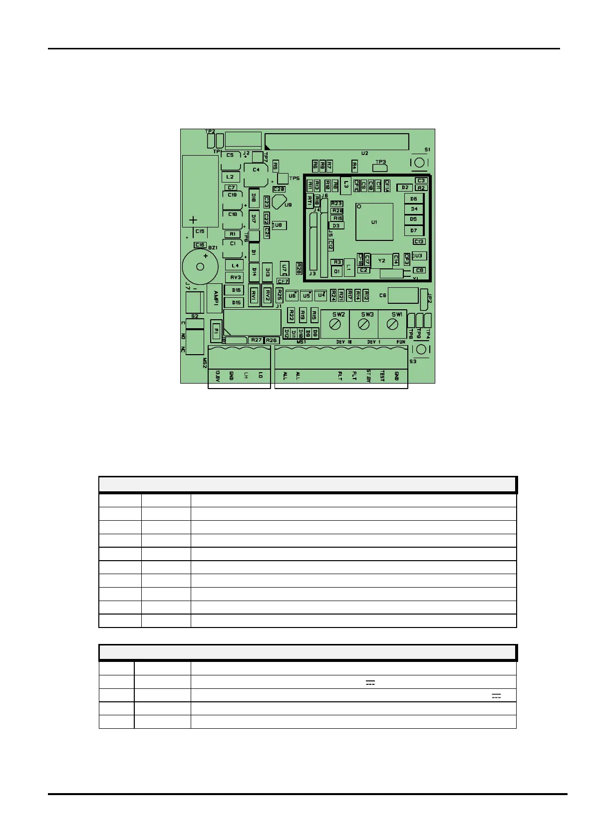
3.1.2 Receiver Circuit
1
Figure 9
Layout of connectors, jumpers, LED and presets on receiver board
The following tables show the connector pin functions on the MANTA Receiver board.
ALL 1 Alarm relay contact (Normally Closed)
ALL 2 Alarm relay contact (Normally Closed)
TMP Tamper relay contact (Normally Closed) + bulb contact
Fault relay contact (Normally Closed)
Fault relay contact (Normally Closed)
ST BY Auxiliary input for Stand-By command (Norm. Open from GND)
Auxiliary input for Test command (Norm. Open from GND)
Ground auxiliary connection
RECEIVER TERMINAL BLOCK MS
GND 1 Negative Power Supply and Ground connection for Data (0 V )