EasyManua.ls Logo

cias MANTA - Page 44

cias MANTA
Print Icon
To Next Page IconTo Next Page
To Previous Page IconTo Previous Page
Loading...
CIAS Elettronica S.r.l. Ed. 1.5
Installation Handbook Page 43 of 57 MANTA 50 – 80
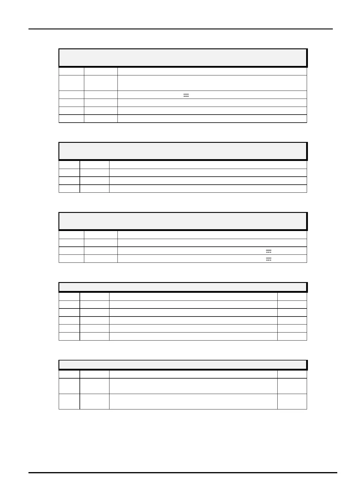
RECEIVER CONNECTOR J1
10 pin Connector for
local
PC Serial Line connection
WAVE
-
TEST
2
Term
Sym
bol
Function
1-2-4-
6
-
8
-
10
N.C.
Not Connected
3
+13,8 Power Supply (13,8 V )
5
LO
Low Line for RS 485
7
LH
High Line for RS 485
9
GND
Ground
RECEIVER CONNECTOR J2
Connector for MW detector
Term
Symbol
Funct
ion
1
GND
Ground connection for MW
detector
2
DET Connection for MW detector
3
GND
Ground connection for MW
detector
RECEIVER CONNECTOR J7
Connector for
External Buzzer
Term
Symbol
Fun
ction
1
COM
Command
for
external
buzzer
2
+13,8
Power Suppl
y voltage for external buzzer (+13,8 V
)
3
+13,8 Power Supply voltage for external buzzer (+13,8 V )
RECEIVER LEDS
Symbol
Function
Default
1
D12 Alarm indication
OFF
2
D
11
Tamper in
dication
OFF
3
D
10
Fault indication
OFF
4
D9 Alignment and setting functions
OFF
5
D
8
Alignment and setting functions
OFF
RECEIVER JUMPERS
Symbol
Function
Default
1
Jp1 RS485 Line termination (Jp1 position 1/2 = line NOT
terminated)
1/2
Closed
2
Jp2 Enable for FW download (Jp2 position 2/3 = FW
download NOT enabled)
2/3
Closed

Related product manuals