CIAS Elettronica S.r.l. Ed. 1.5
Installation Handbook Page 55 of 57 MANTA 50 – 80
5 MAINTENANCE AND ASSISTANCE
5.1 Troubleshooting
In case of false alarms, check the parameters recorded during the
Installation
phase (on
attached
Test Sheet
), if there are differences outside the permitted limits check the related
points in chapter "Adjustment and Testing (4)" again.
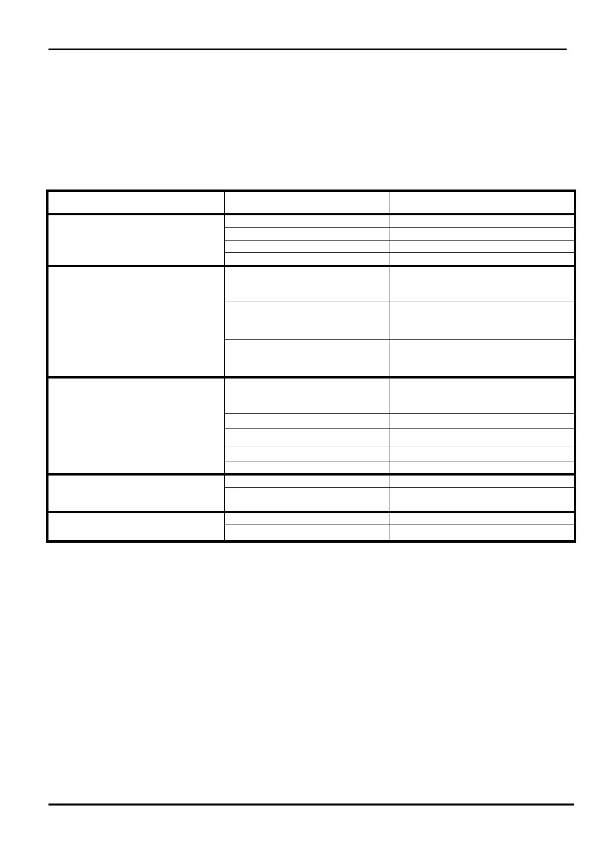
Defect Possible Cause Possible Solution
Fault Led ON Power too high or too low Check the power supply voltage
Temperature too high or too low Check the temperature of the barrier
Tx Oscillator Fault Change the Oscillator
Tx or Rx failure Change the Electronic board
Alarm Led ON Movement or obstacles in the
protected field
Check that the protected field is free
from obstacles and free from objects
and/or person moving.
Barrier not properly aligned Re-do the alignment procedure as
described in points: a,b,c,d,e,f,g,h,i of
charter 4.1.2
Wrong channel selection Re-do the Channel acknowledge
procedure as described in point b, j of
charter 4.1.2
High AGC Voltage Barrier not properly aligned Re-do the alignment procedure as
described in points: a,b,c,d,e,f,g,h,i,j
of charter 4.1.2
obstacles in the protected field Remove obstacles
Too low signal transmitted Check the transmitter
Rx circuit fault Change the Rx circuit
Rx MW part fault Change the RX MW part
Tamper Led ON Micro switch open Check the micro switch position
Tilt bulb in wrong position Check the position of the tilt bulb
(Vertical)
Fault Led ON only on TX circuit BF Oscillator Fault Change the TX circuit
MW oscillator Fault Change the MW part
5.2 Maintenance kits
The
Maintenance Kits
comprise circuit boards fitted with microwave cavities and replacement is
simple:
The substitution of circuit and cavity on either transmitter or receiver heads will not
change the alignment of the heads then no re-alignment is required