EN
EN - 7 NA 15.15 B
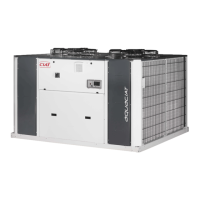
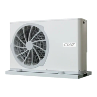
13 - ElECTRICAL CONNECTIONS
The CONDENCIAT CL2 units are designed in conformity with the low voltage directive and more specifically in compliance with
the international standards EN 60335-1, EN 60335-2-40, EN 61000-6-1, EN 61000-6-2, EN 61000-6-3 and EN 61000-6-4.
When making the electrical connections, disconnect the unit from the power supply before carrying out any handling work.
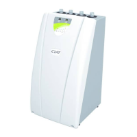
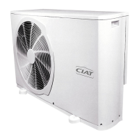
Open the top of the unit as shown below and do the electrical connections in accordance with the supplied wiring diagram, and
tighten the terminals carefully.
D
D
Remove the central screw
(at the back)
Unclip at each end Remove the cover
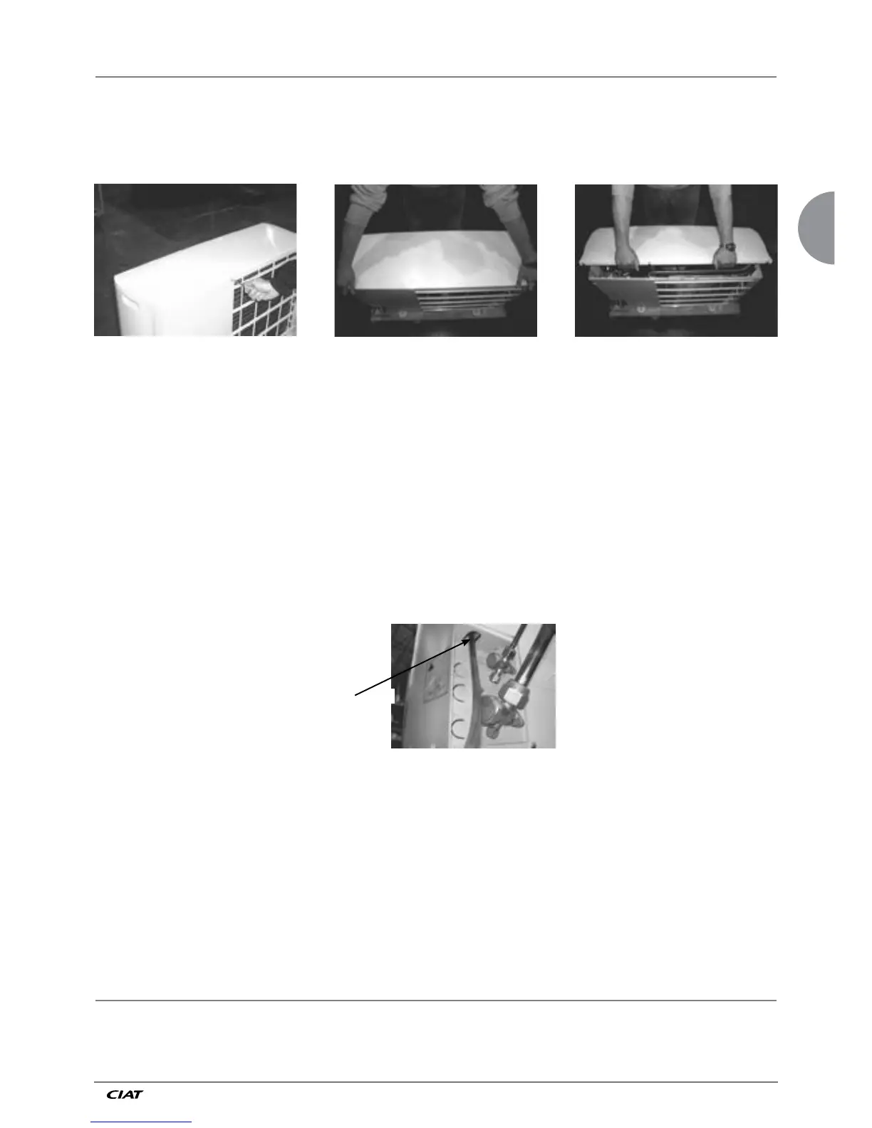
Cable way
Detail for the supply of the electrical panel
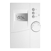
- Input for external control : this potential-free contact positioned between terminals 1 and 2 is used to start the compressor
- closed contact = run
- open contact = stop
To avoid damaging the compressor, do not exceed 10 ON / OFF cycles per hour
Data to be taken in account for the quality of the contact : the current which goes through is 35 mA under 230V.
- Fault outputs: they indicate the actuation of one of the 2 pressure switches.
Contacts characteristics : - Minimum current : 10 mA
- Minimum voltage : 10 V
- Load : 4000 Va in AC1, 750 VA in AC15
14 - SETTING OF SAFETY AND CONTROL DEVICES
High pressure switch, manual reset : start at 41.5 bars.
Low pressure switch, automatic reset : actuation at 2.5 bars / release at 4.5 bars.
Condensing pressure control : control at 24 bars (factory setting).
- The electrical characteristics of the available power supply available must correspond to the values shown on the manufacturer’s
plate.
- The electrical power must meet the following requirements for all the models:
230 V
+6
-10
% 50 Hz or 400 V
+6
-10
% 50 Hz
- All the wiring installations must be made in accordance with the regulations in force on the site of installation
(in France, NF C 15100).
The appropriate cable must be selected depending on the maximum current absorbed by the unit (see the electrical characteristics
table), the distance between the unit and the starting point of the power supply, the protection upstream, the operating system
used for the neutral terminal.
IMPORTANT : Connect the earthing circuit before making any other electrical connections.
The installation must be fitted with a master isolating switch.
 Loading...