- 11 -
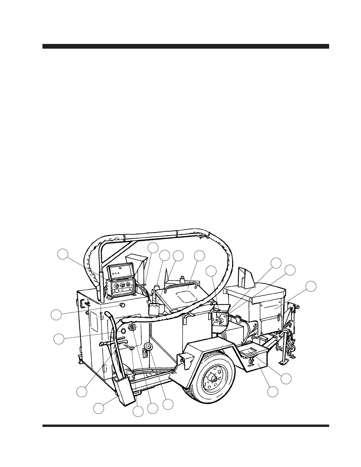
Controls and Their Functions
12) Air Cleanout Valve (optional): Connect air line or solvent line to this connector to
flush out system. This valve should remain closed at all times other than cleanout.
13) Temperature Control Box: This control allows the operator to set the desired oil
temperature. The setting will be maintained automatically.
14) Engine Throttle: Refer to Engine Manual for start up and maintenance procedures.
15) Cabinet Temperature Gauge: Indicates the temperature inside the cabinet. Do not
exceed 320º F. If conditions permit exceeding this temperature, open cabinet door.
16) Thermal Regulating Gate: Lift lever (A) to open gate (B) which will direct hot air to
cabinet to heat pump and plumbing.
17) Battery Box: Battery and related electrical components are located inside.
18) Ignition Access Door: On Diesel models, lift this door for access to ignition key.
19) Wand Holder: On models with the electrically heated hose, the wand is placed into
this holder.
1
7
12
8
19
6
15
13
4
2
16
3
10
9
14
11
18
17