- 18 -
Adjusting Burner Nozzle, Electrode and Head Position
Your CIMLINE 110, 230 or 410 Melter is equipped with a model ADC burner. Each unit
comes with a nozzle, electrode and head position gauge. For optimum performance, the
steps below should be performed periodically. The burner must be removed from the
combustion chamber.
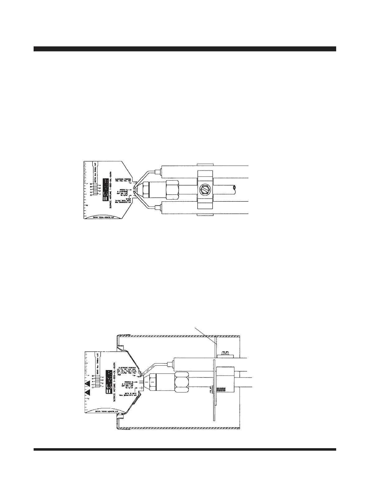
Step 1: Setting the Electrode Gap
Check electrodes to see if the gap is aligned with the lines on the gauge. The gap should
be
from 1/8" to 5/32" as shown below. Bend the electrodes slightly if required. If the elec-
trodes are way out of line, you may have to remove the head and realign as described in
Step 3.
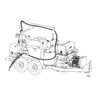
Step 2: Inspecting Nozzle Concentricity
The nozzle should be approximately centered within the head. Insert the gauge as shown.
The center of the nozzle should be aligned with the center line. Rotate the gauge and
check alignment from several locations. BE CAREFUL NOT TO SCRATCH THE SUR-
FACE. If it is not concentric, you may have to replace or straighten center bracket.
P/N 152668
Centering bracket