MC55i Terminal Hardware Interface Description
3.6 RS-232 Interface
32
MC55i_Terminal_HD_v01.201a Page 25 of 47 2010-04-16
Confidential / Released
3.6 RS-232 Interface
Via RS-232 interface, the host controller controls the MC55i Terminal and transports data.
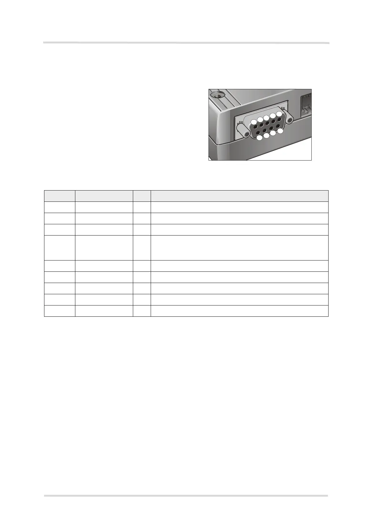
Figure 5: Pin assignment RS-232 (D-Sub 9-pole female)
MC55i Terminal is designed for use as a DCE. Based on the conventions for DCE-DTE con-
nections it communicates with the customer application (DTE) using the following signals:
• Port TxD @ application sends data to TXD of MC55i Terminal
• Port RxD @ application receives data from RXD of MC55i Terminal
The RS-232 interface is implemented as a serial asynchronous transmitter and receiver con-
forming to ITU-T V.24 Interchange Circuits DCE. It is configured for 8 data bits, no parity and
1 stop bit, and can be operated at bit rates from 300bps to 115kbps. Autobauding supports bit
rates from 1.2kbps to 115kbps. Hardware handshake using the /RTS and /CTS signals and
XON/XOFF software flow control are supported.
In addition, the modem control signals /DTR, /DSR, /DCD and /RING are available. The modem
control signal RING (Ring Indication) can be used to indicate, to the cellular device application,
that a call or Unsolicited Result Code (URC) is received. There are different modes of opera-
tion, which can be set with AT commands.
Note: The /DTR signal will only be polled once per second from the internal firmware of MC55i.
Table 10: 9-pole D-Sub (female) RS-232
Pin no. Signal name I/O Function
1 /DCD O Data Carrier Detected
2 /RXD O Receive Data
3 /TXD I Transmit Data
4 /DTR I Data Terminal Ready
Attention: The ignition of MC55i Terminal is activated via a ris-
ing edge of high potential (+3 ... +15 V)
5 GND - Ground
6 /DSR O Data Set Ready
7 /RTS I Request To Send
8 /CTS O Clear To Send
9 /RING O Ring Indication
3
2
1
8
6
7