MC55i Terminal Hardware Interface Description
4.7 Antenna Interface
41
MC55i_Terminal_HD_v01.201a Page 41 of 47 2010-04-16
Confidential / Released
4.7 Antenna Interface
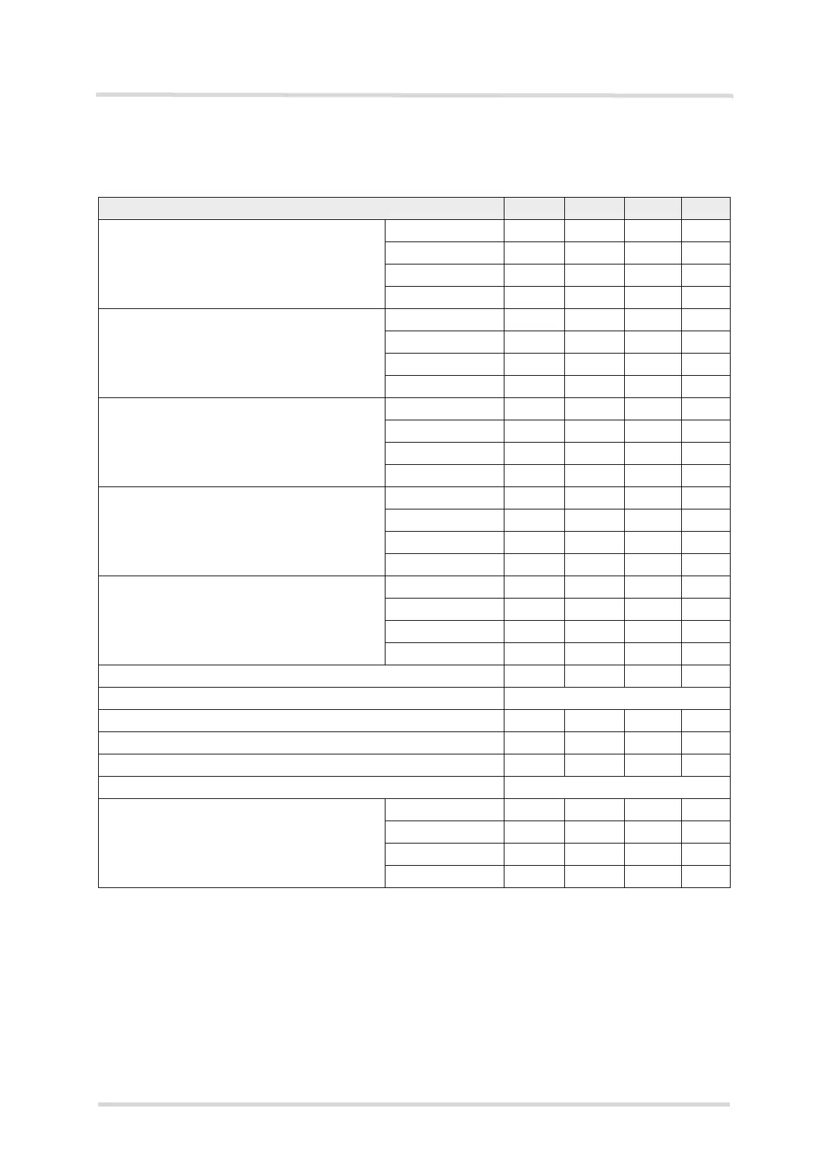
Table 22: Antenna interface characteristics
Parameter Min Typ Max Unit
Frequency range GSM 850 824 849 MHz
Uplink (MS BTS) E-GSM 900 880 915 MHz
GSM 1800 1710 1785 MHz
GSM 1900 1850 1910 MHz
Frequency range GSM 850 869 894 MHz
Downlink (BTS MS) E-GSM 900 925 960 MHz
GSM 1800 1805 1880 MHz
GSM 1900 1930 1990 MHz
RF power @ ARP with 50
load GSM 850
1
1.
Power control level PCL 5
31 33 35 dBm
E-GSM 900
1
31 33 35 dBm
GSM 1800
2
2.
Power control level PCL 0
28 30 32 dBm
GSM 1900
2
28 30 32 dBm
Number of carriers GSM 850 124
E-GSM 900 174
GSM 1800 374
GSM 1900 299
Duplex spacing GSM 850 45 MHz
E-GSM 900 45 MHz
GSM 1800 95 MHz
GSM 1900 80 MHz
Carrier spacing 200 kHz
Multiplex, Duplex TDMA / FDMA, FDD
Time slots per TDMA frame 8
Frame duration 4.615 ms
Time slot duration 577 µs
Modulation GMSK
Receiver input sensitivity @ ARP
BER Class II < 2.4% (static input level)
GSM 850 -102
3
3.
Under fading conditions
-107
4
4.
Typical value is at least -107dBm.
dBm
E-GSM 900 -102
3
-107
4
dBm
GSM 1800 -102
3
-107
4
dBm
GSM 1900 -102
3
-107
4
dBm