MC55i Terminal Hardware Interface Description
3.10 Antenna Interface
32
MC55i_Terminal_HD_v01.201a Page 31 of 47 2010-04-16
Confidential / Released
3.10 Antenna Interface
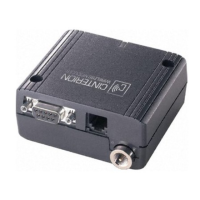
The external antenna is connected via the terminal’s FME jack (male).
Figure 10: Antenna interface
An internal antenna cable adapts the antenna reference point (antenna connector type U.FL-
R-SMT from Hirose) to the FME (male) connector. The position of the antenna reference point
can be seen in Figure 2.
• Cable loss of the internal cable
<0.4dB @ 900MHz
<0.6dB @ 1800MHz
• The system impedance is 50
.
• In every case, for good RF performance the return loss of the customer application’s
antenna should be better than 10dB (VSWR < 2).
• MC55i Terminal withstands a total mismatch at this connector when transmitting with power
control level for maximum RF power.
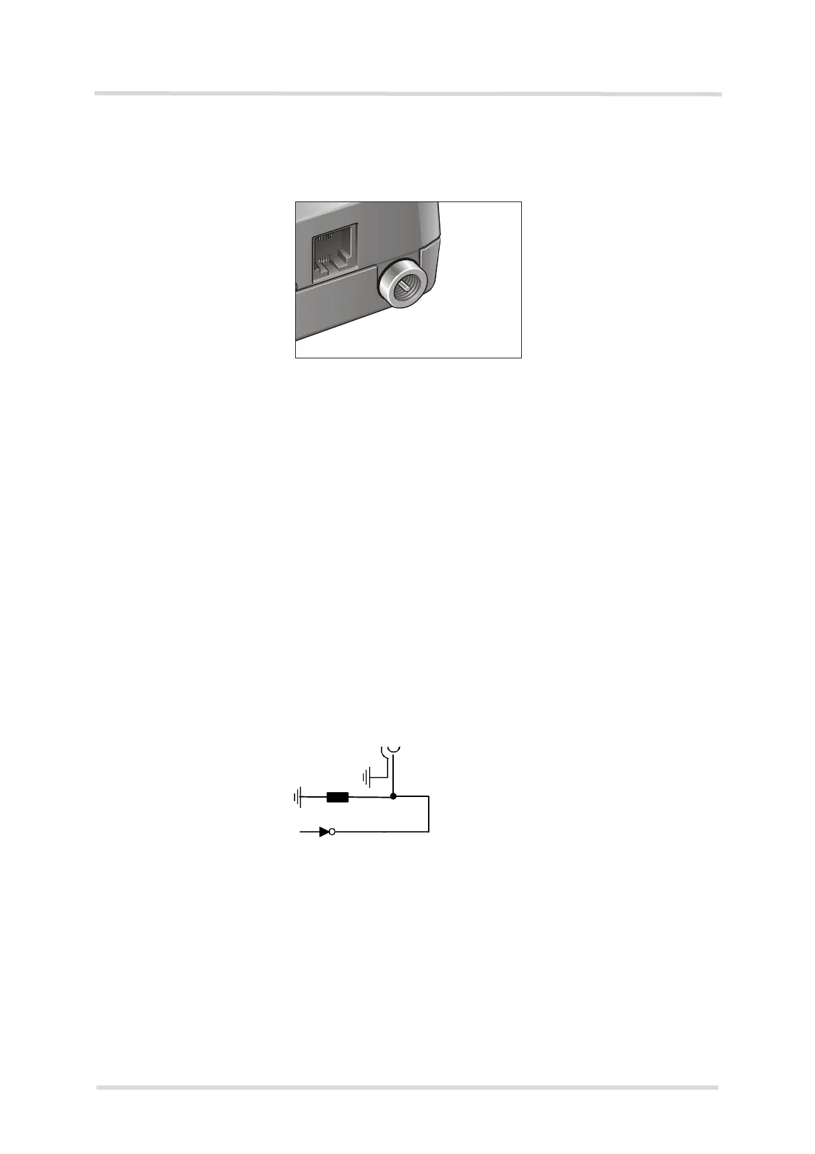
Inside the MC55i module a 27nH inductor to ground provides additional ESD protection to the
antenna connector. For details see Figure 11. To protect the inductor from damage no DC volt-
age must be applied to the antenna circuit.
Figure 11: Antenna connector circuit on MC55i module
EMC immunity complies with the vehicular environment requirements according to
EN 301 489-7.
U.FL-R-SMT connector (from Hirose)
TRX In / Output
L (27nH)