1-3
Cisco Connected Grid Routers 2010 Hardware Installation Guide
OL-21559-01
Chapter 1 Overview of the Router
Hardware Features
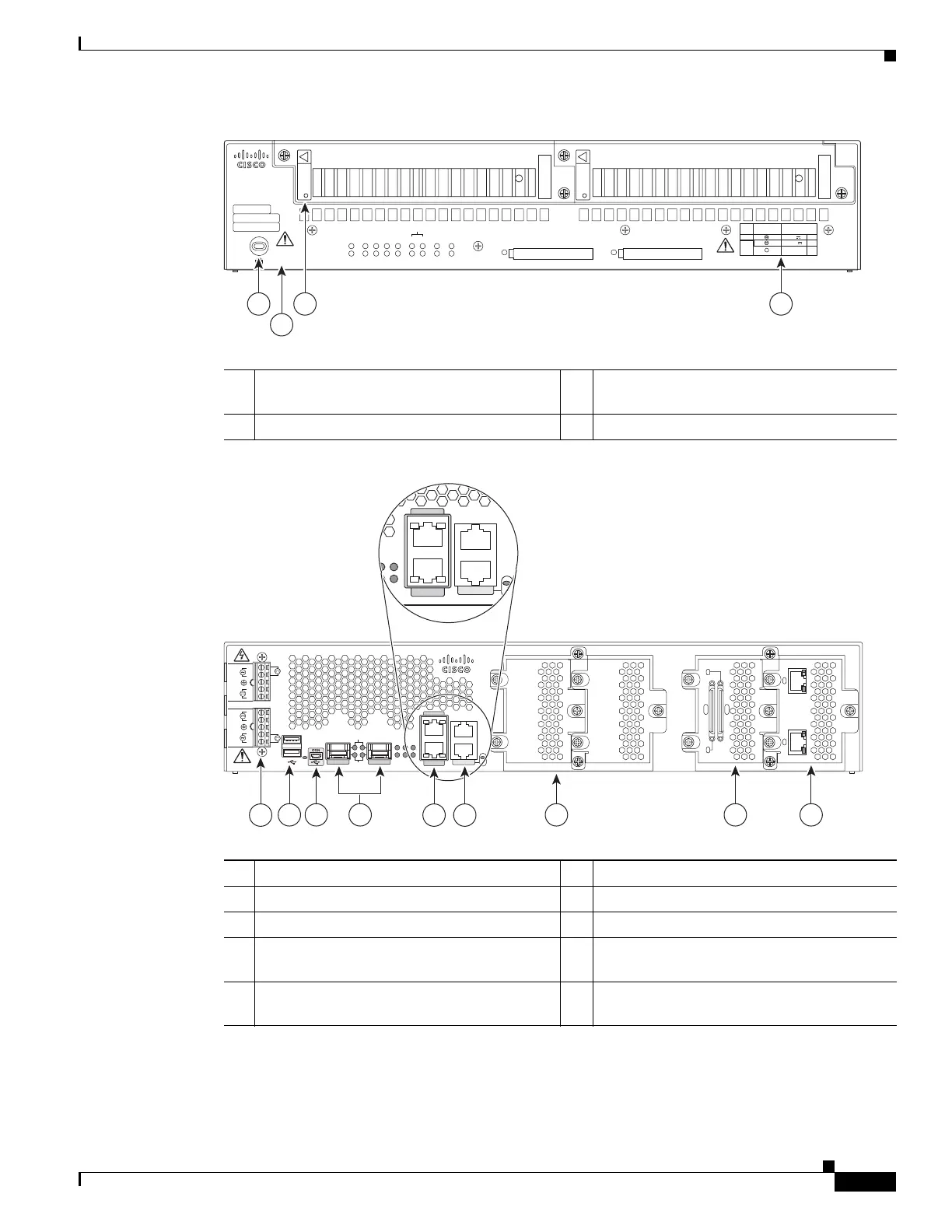
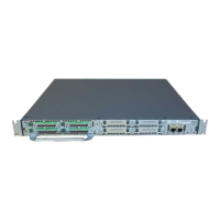
Figure 1-4 Power Supply Side View Features and Functions on the Cisco 2010 CGR
Figure 1-5 Cable Side View Features and Functions on the Cisco 2010 CGR
248945
PSU1 PSU2
PSU OK
PWR-150W-HV
PSU OK
PWR-150W-HV
SYS SPD SPD SPD SPD 2 0 1
USB
CON
ACT
SFP
0/1
EN
SFP
0/0
EN
GE
0/1
LINK
GE
0/0
LINK
PSU
231
CONSOLE
SLOT
CF1
DO NOT REMOVE DURING
NETWORK OPERATION
CF0
DO NOT REMOVE DURING
NETWORK OPERATION
Cisco Connected Grid Router 2000 Series
CAUTION: This unit may have more than
one power source. Disconnect all power
sources before servicing to avoid
electric shock.
PS
Typ e
Input Terminal
Symbol
Input Rating
Per Source
Lo V DC
Hi V DC
Lo 24 - 60 V 10A
100-250V
2A
100-240V
~
2A
50-60 Hz
Hi
or
V AC
~
1
2
3 4
1 Kensington security slot 2 Caution label and statement for multiple
power source
3 Power supply unit 1 (PSU1) label 4 Power supply power range label
SFP 0/0
GE 0/0
GE 0/1
SFP 0/1
CONSOLE
PSU2
L
N
N
L
+
Lo
-
-
Lo
+
-
HI
+
+
HI
-
Cisco CGR 2010
0
1
EN
EN
SPD
CF
1
PS
2ACT
SYS 0 1
SL
SL
AUX
EN
SLOT 3 SLOT 2 SLOT 1 SLOT 0
CONN CONN
0-3
4-7
GRWIC–8A/8-232
GRWIC–2CE1T1-PRI
CD/LP AL CD/LP AL
P1 P0
PSU1
GE 0/0
GE 0/1
CONSOLE
CF
1
PS
2
01
SL
SL
AUX
EN
1 65
2 3 7 98
4
277445
1 Terminal blocks
1
1. Enables AC power, high-voltage DC power, and low-voltage DC power input for dual power supplies.
2 USB0 and USB1 (1, top)
3 USB
2
serial console port
2. USB = Universal serial bus.
4 SFP0/0 and SFP0/1
5 100/1000 Ethernet port (GE0/0 and GE0/1) 6 RJ-45 aux port and serial console port
7 GRWIC slot
3
3 (slot cover showing)
3. Four slots with two removable dividers allow the following install options: 4 single-wide GRWICs; 2 single-wide GRWICs
and 1 double-wide GRWIC cover; 2 double-wide GRWIC covers (double-wide GRWIC modules are not yet supported on the
Cisco 2010 CGR).
8 GRWIC slot 1 (8-port dual RS-232 serial
interface showing)
9 GRWIC slot 0
4
(T1/E1 dual port interface
showing)
5