1-8
Cisco Connected Grid Routers 2010 Hardware Installation Guide
OL-21559-01
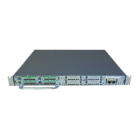
Chapter 1 Overview of the Router
Specifications
Specifications
To view specifications for the 2010 CGR router, see the Cisco 2010 Connected Grid Router data sheet at:
http://www.cisco.com/en/US/prod/collateral/routers/ps10967/ps10977/data_sheet_c78_593509.html
Ta b l e 1-3 Cisco 2010 CGR LED Indicators
LED Color Description Panel
PSU Green Valid output. Power supply
side
Red Invalid output.
Blinking red Invalid input
GRWIC Green System is running. Power supply
side and cable
side panel
Amber System is not running.
SYS Solid green Solid green indicates normal operation. Power supply
side and cable
side panel
Blinking green System is booting or is in ROM monitor mode.
Amber System error.
Off Power is off or system board is faulty.
ACT Solid or blinking
green
Solid or blinking indicates packet activity between
the forwarding and routing engine and any I/O
port.
Power supply
side and cable
side panel
Off No packet transfers are occurring.
RJ-45 CON Green Serial console is active. Cable side
USB CON Green USB console is active. Cable side
GE0/GE1:
Link
Green Solid green indicates the Ethernet port has a link
partner.
Cable side
SFP0
link/SFP1
link
Off Not present. Power supply
side
Green Present and enabled.
Amber Present with failure.
SFP0
SPD/SFP1
SPD
Off No link. Cable side
Green Note Blink indicates port speed.
blinking 2 blinks before pause – 100Mbps link speed.
3 blinks before pause – 1000Mbps link speed.
CF0/CF1 Green Flash memory is being accessed; do not eject the
compact flash memory card.
Cable side
Amber Compact flash error. Cable side
Off Flash memory is not being accessed; okay to eject
the compact flash memory card.
Cable side