Replacing the Cover
Take the following steps to replace the cover:
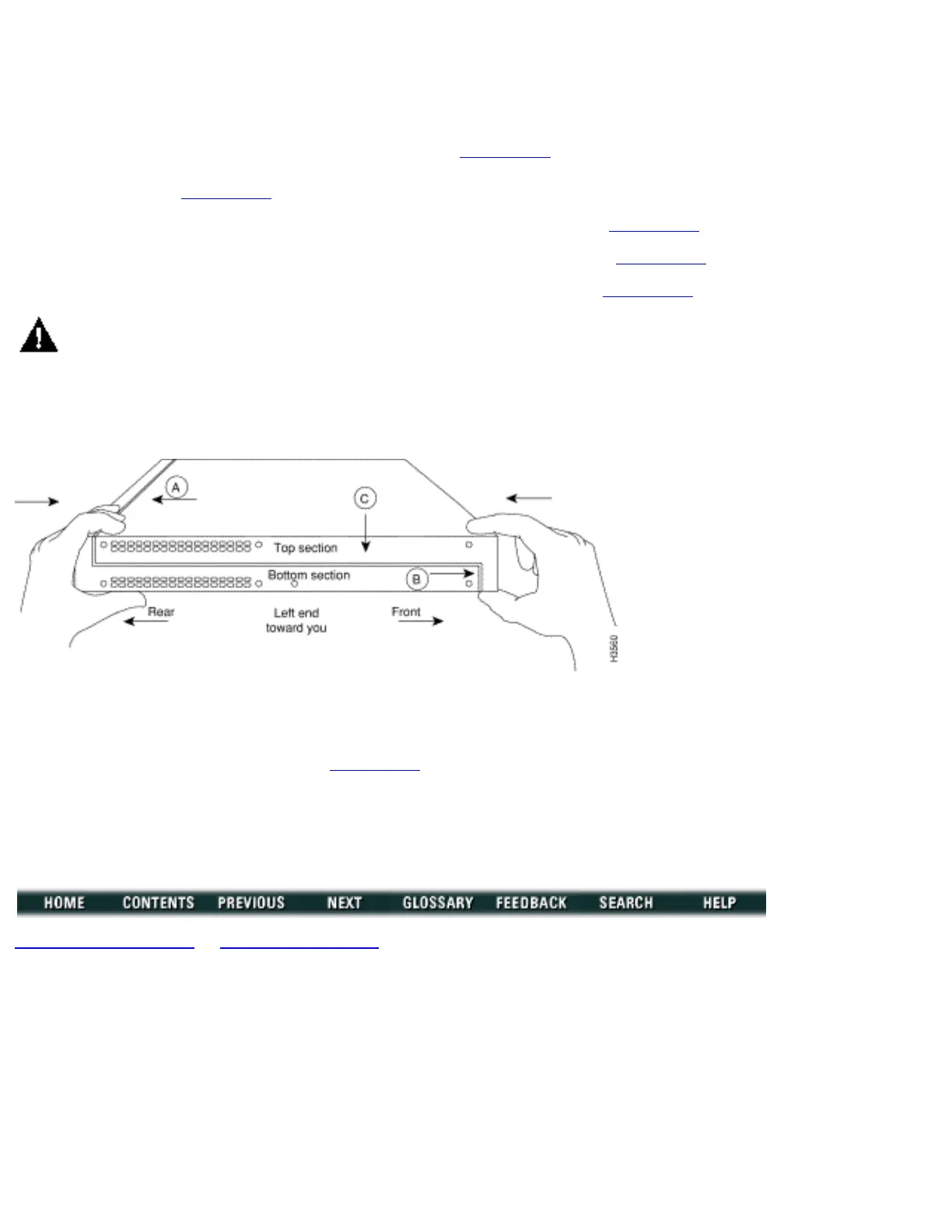
Step 1 Position the two chassis sections, as shown in Figure B-5.
Step 2 Referring to Figure B-5, press the two chassis sections together and ensure the following:
The top section fits into the rear of the bottom section. (See A in Figure B-5.)●
The bottom section fits into the front of the top section. (See B in Figure B-5.)●
Each side of the top and bottom sections fits together. (See C in Figure B-5.)●
Caution To fit the two sections together, it may be necessary to work them together at one end and
then the other, working back and forth; however, use care to prevent bending the chassis edges.
Figure B-5: Replacing the Chassis Cover
Step 3 When the two sections fit together snugly, turn the chassis so that the bottom is facing up, with the
front panel toward you.
Step 4 Replace the cover screw. (See Figure B-1.) Tighten the screw to no more than 8 or 9 inch/pounds of
torque.
Step 5 Reinstall the chassis on the wall, rack, desktop, or table.
Step 6 Replace all cables.
Copyright 1989-1997 © Cisco Systems Inc.
http://www.cisco.com/univercd/cc/td/doc/product/access/acs_fix/cis2500/2520/2520_23/c2520mnt.htm (7 of 7) [10/27/2000 3:08:02 PM]

 Loading...