1
Pin 1 is connected internally to Pin 8.
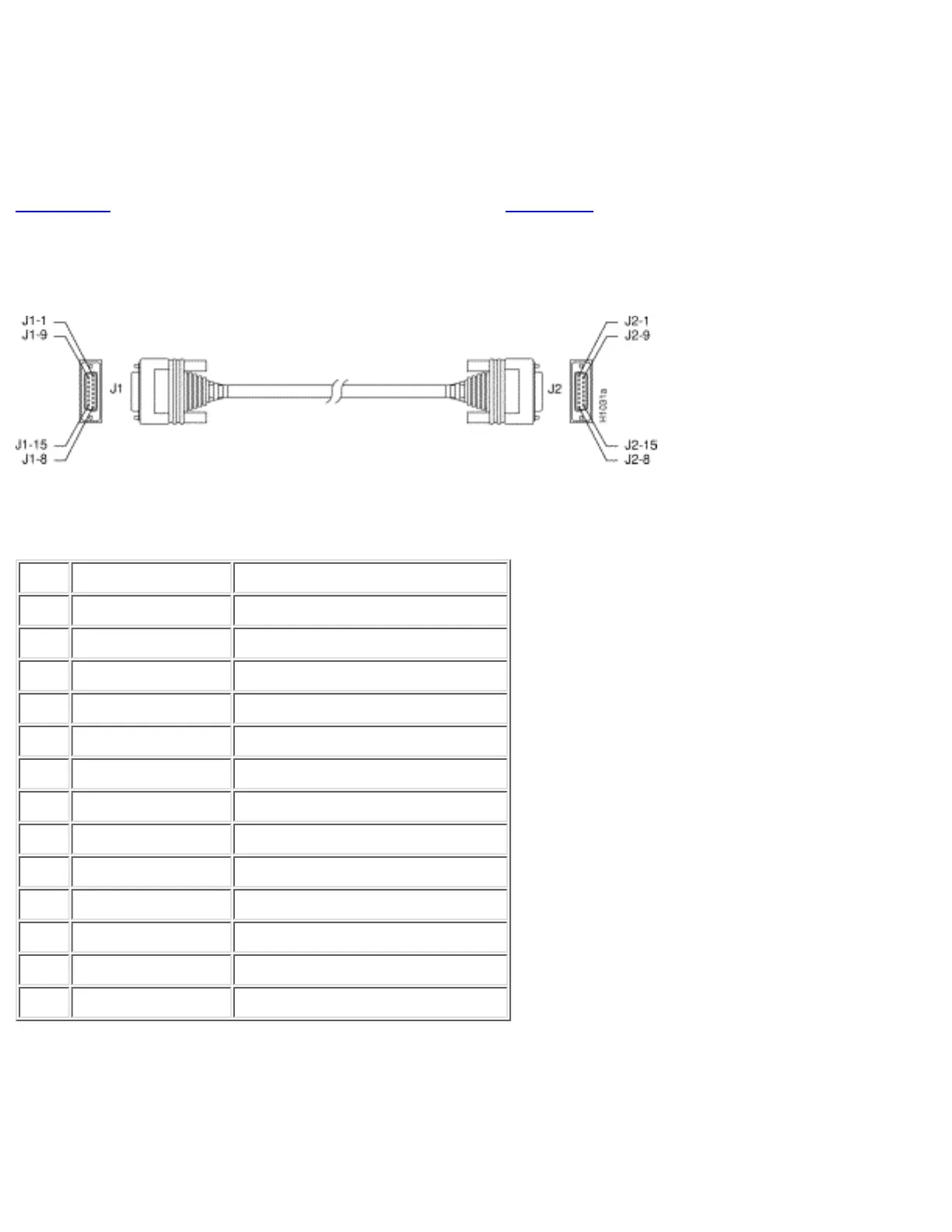
Ethernet Cable Assembly and Pinouts
This section describes the pinouts for an Ethernet AUI cable.
Figure C-5 shows an Ethernet AUI cable assembly, and Table C-4 lists the cable pinouts.
Figure C-5: Ethernet AUI Cable Assembly
Table C-4: Ethernet AUI Cable Pinouts (DB-15)
(Continued)
Pin Ethernet Circuit Signal
3 DO-A Data Out Circuit A
10 DO-B Data Out Circuit B
11 DO-S Data Out Circuit Shield
5 DI-A Data In Circuit A
12 DI-B Data In Circuit B
4 DI-S Data In Circuit Shield
2 CI-A Control In Circuit A
9 CI-B Control In Circuit B
1 CI-S Control In Circuit Shield
6 VC Voltage Common
13 VP Voltage Plus
14 VS Voltage Shield (L25 and M25)
Shell PG Protective Ground
http://www.cisco.com/univercd/cc/td/doc/product/access/acs_fix/cis2500/2520/2520_23/c2520cab.htm (5 of 17) [10/27/2000 3:08:10 PM]

 Loading...