TxD 3 6 3 RxD
GND 4 5 7 GND
GND 5 4 7 GND
RxD 6 3 2 TxD
DSR 7 2 20 DTR
CTS 81 1 4 RTS
1
You can use the same cabling to connect a console to the auxiliary port.
2
Pin 1 is connected internally to Pin 8.
Auxiliary Port Signals and Pinouts
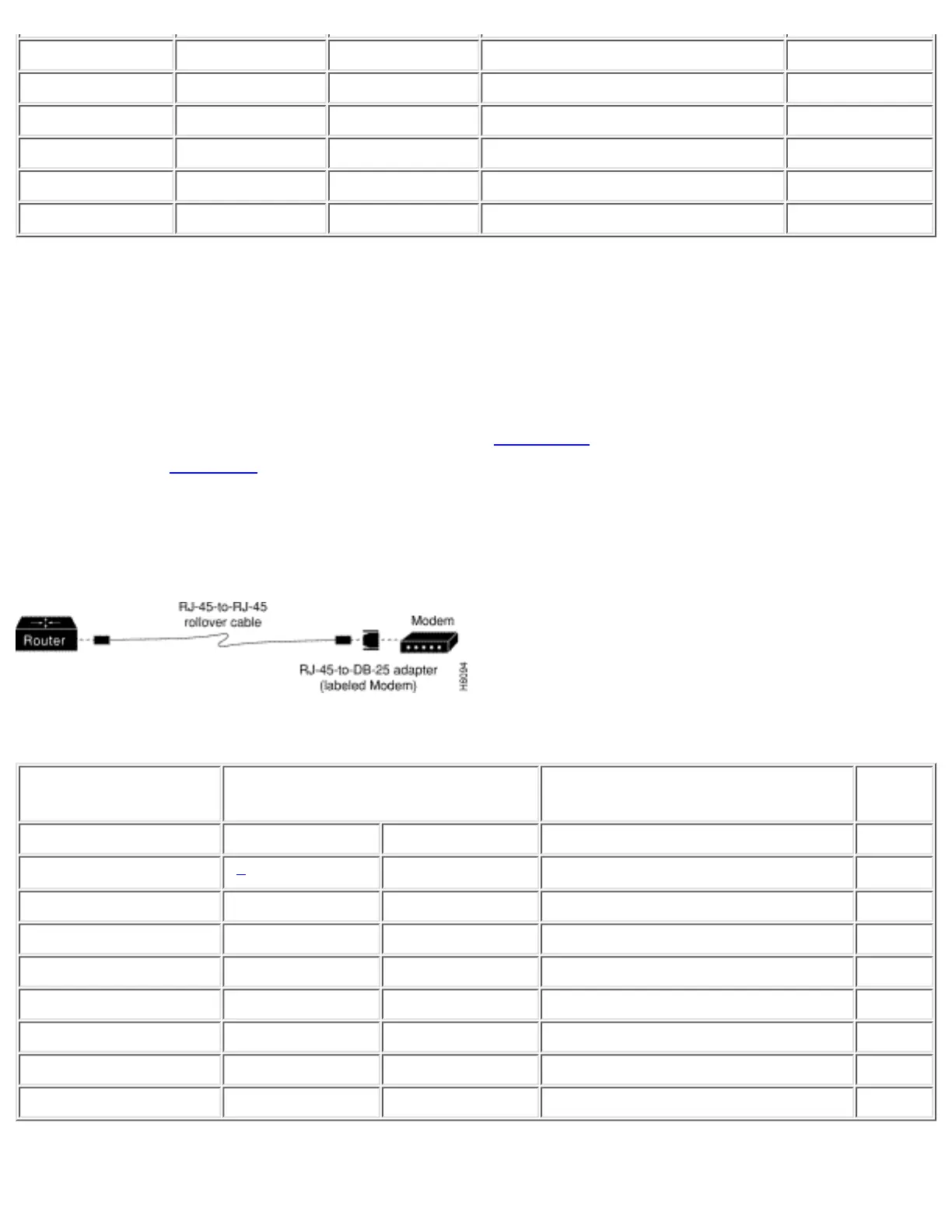
Use the thin, flat, RJ-45-to-RJ-45 roll-over cable and RJ-45-to-DB-25 male DCE adapter (labeled
"MODEM") to connect the auxiliary port to a modem. Figure C-4 shows how to connect the auxiliary
port to a modem. Table C-3 lists the pinouts for the asynchronous serial auxiliary port, the
RJ-45-to-RJ-45 roll-over cable, and the RJ-45-to-DB-25 male DCE adapter (labeled "MODEM").
Figure C-4: Connecting the Auxiliary Port to a Modem
Table C-3: Auxiliary Port Signaling and Cabling Using a DB-25 Adapter
Auxiliary Port
(DTE)
RJ-45-to-RJ-45 Roll-Over Cable RJ-45-to-DB-25 Modem Adapter Modem
Signal RJ-45 Pin RJ-45 Pin DB-25 Pin Signal
RTS
1
1
8 4 RTS
DTR 2 7 20 DTR
TxD 3 6 3 TxD
GND 4 5 7 GND
GND 5 4 7 GND
RxD 6 3 2 RxD
DSR 7 2 8 DCD
CTS 81 1 5 CTS
http://www.cisco.com/univercd/cc/td/doc/product/access/acs_fix/cis2500/2520/2520_23/c2520cab.htm (4 of 17) [10/27/2000 3:08:10 PM]

 Loading...