V.35
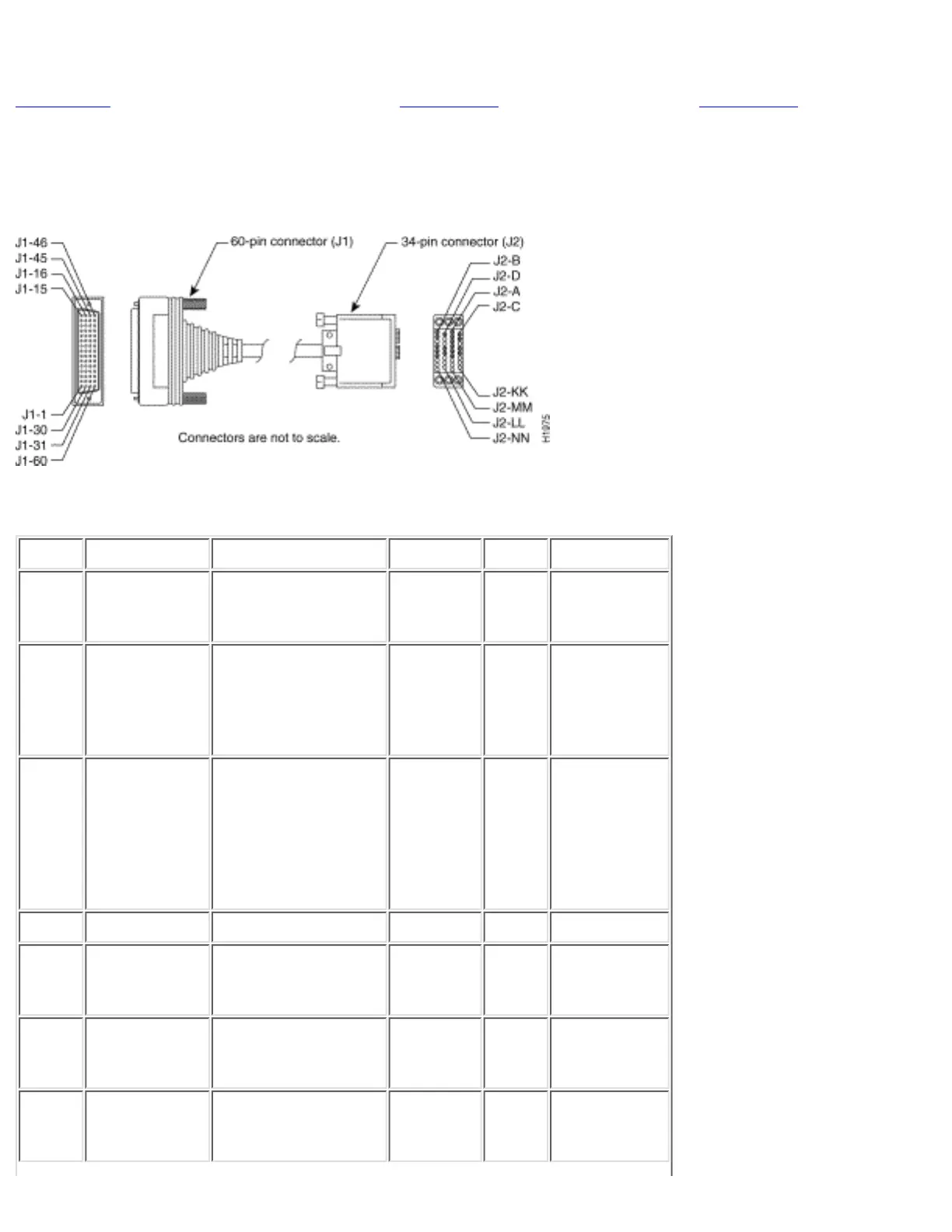
Figure C-9 shows the V.35 cable assembly. Table C-11 lists the DTE pinouts. Table C-12 lists the DCE
pinouts. Arrows indicate signal direction: --> indicates DTE to DCE, and <-- indicates DCE to DTE.
Figure C-9: V.35 Cable Assembly
Table C-11: V.35 DTE Cable Pinouts (DB-60 to 34-Pin) (Continued)
60 Pin Signal Description Direction 34 Pin Signal
J1-49
J1-48
MODE_1
GND
Shorting group - - -
J1-50
J1-51
J1-52
MODE_0
GND
MODE_DCE
Shorting group - - -
J1-53
J1-54
J1-55
J1-56
TxC/NIL
RxC_TxCE
RxD/TxD
GND
Shorting group - - -
J1-46 Shield_GND Single - J2-A Frame GND
J1-45
Shield
Circuit_GND
-
Twisted pair no. 12 -
-
J2-B
Shield
Circuit GND
-
J1-42
Shield
RTS/CTS
-
Twisted pair no. 9 -->
-
J2-C
Shield
RTS
-
J1-35
Shield
CTS/RTS
-
Twisted pair no. 8 <--
-
J2-D
Shield
CTS
-
http://www.cisco.com/univercd/cc/td/doc/product/access/acs_fix/cis2500/2520/2520_23/c2520cab.htm (13 of 17) [10/27/2000 3:08:10 PM]

 Loading...