C-13
Cisco 3200 Series Router Hardware Reference
OL-5816-10
Appendix C Switch Port Functionality
Storm Control
(132.206.72.28, 224.2.136.89), 00:14:31/00:01:40, flags:CJT
Incoming interface:GigabitEthernet4/8, RPF nbr 10.15.1.20, RPF-MFD
Outgoing interface list:Null
Router#
Note The RPF-MFD flag indicates that the flow is completely hardware switched. The H flag indicates that
the flow is hardware-switched on the outgoing interface.
Storm Control
A packet storm occurs when a large number of broadcast, unicast, or multicast packets are received on
a port. Forwarding these packets can cause the network to slow down or to time out. Storm control is
configured for the switch as a whole, although it operates on a per-interface basis. By default, storm
control is disabled.
Storm control prevents switch ports on a LAN from being disrupted by a broadcast, multicast, or unicast
storm on one of the interfaces. A LAN storm occurs when packets flood the LAN, creating excessive
traffic and degrading network performance. Errors in the protocol-stack implementation or in the
network configuration can cause a storm.
Storm control monitors incoming traffic statistics over a time period and compares the measurement with
a predefined suppression level threshold. The threshold represents the percentage of the total available
bandwidth of the port. If the threshold of a traffic type is reached, further traffic of that type is suppressed
until the incoming traffic falls below the threshold level.
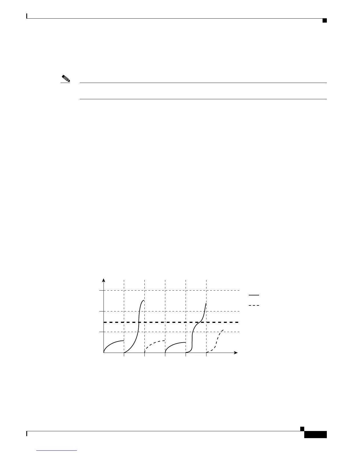
The graph in Figure C-6 shows broadcast traffic patterns on an interface over a given period of time. In this
example, the broadcast traffic exceeded the configured threshold between time intervals T1 and T2 and
between intervals T4 and T5. When the amount of specified traffic exceeds the threshold, all traffic of that
kind is dropped. Therefore, broadcast traffic is blocked during those intervals. At the next time interval, if
broadcast traffic does not exceed the threshold, it is again forwarded.
Figure C-6 Broadcast Suppression Example
When storm control is enabled, the switch monitors the packets that are passing from an interface to the
switching bus and determines whether the packet is unicast, multicast, or broadcast. The switch monitors
the number of broadcast, multicast, or unicast packets received within the 1-second time interval, and
Total
number of
broadcast
packets
or bytes
Forwarded traffic
0T1
Threshold
T2 T4 T5
46651
T3 Time
Blocked traffic

 Loading...