5-4
Cisco 3200 Series Router Hardware Reference
OL-5816-10
Chapter 5 Serial Mobile Interface Card
2-port SMIC Rotary Switch Positions
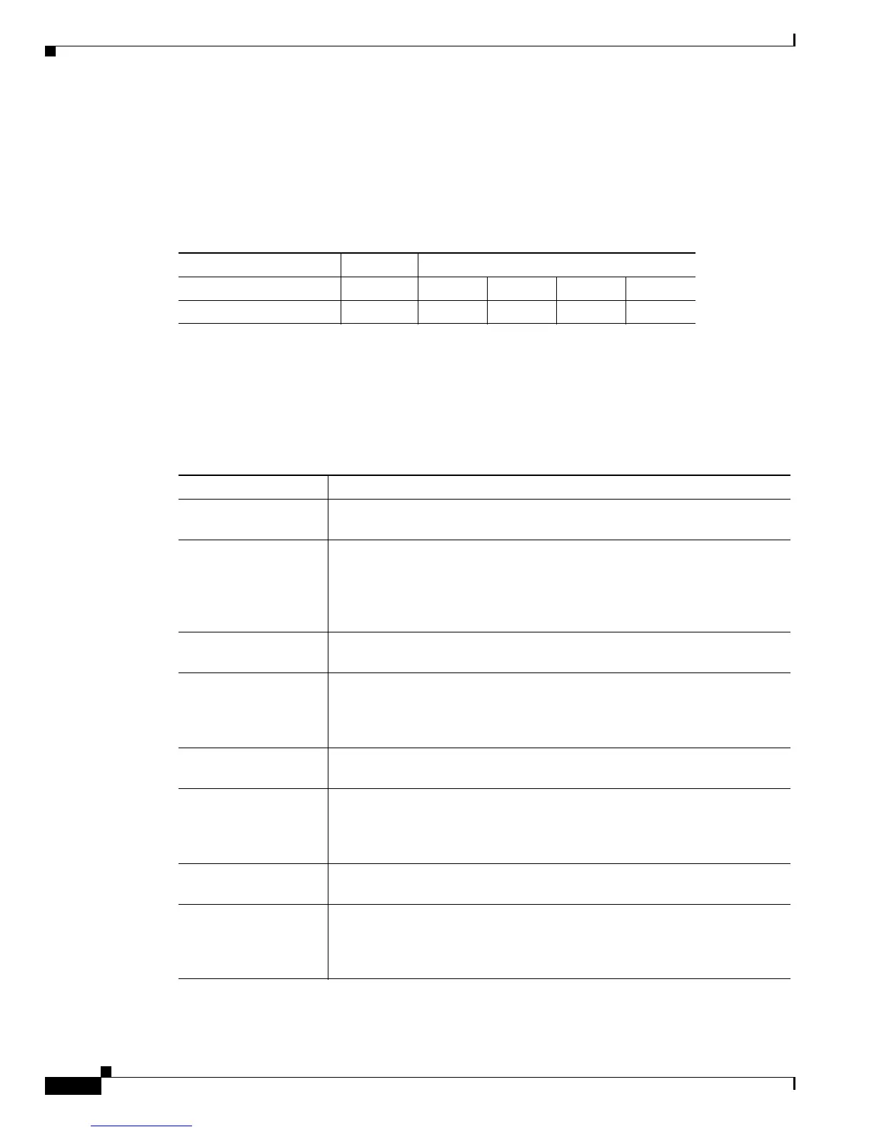
Table 5-4 shows the 2-port SMIC serial signal assignments. The position of the rotary switch determines
the port assignments. Although the rotary switch has 8 positions, only 1 of 2 positions can be selected.
The rotary switch position should be unique for each mobile interface card (MIC) card.
SMIC LED Signals
Table 5-5 shows the LED signals that are supported on the SMIC, along with the corresponding
functions. Serial 2 and Serial 3 apply to the 4-port SMIC only.
Ta b l e 5-4 2-port SMIC Rotary Switch Positions and Serial Set Signal Assignments
Rotary Switch Position MIC Slot Signal Assignments
0 1 Serial 1/0 Serial 1/1 Serial 1/2 Serial 1/3
1 2 Serial 2/0 Serial 2/1 Serial 2/2 Serial 2/3
Ta b l e 5-5 SMIC LED Functions
LED Function
SERIAL0 ACTIVITY Blinks once when a packet is either transmitted from or received on Serial 0.
Originates from Header 5.
SERIAL0 LINK Indicates the status of Serial 0. Originates from Header 5. The LED is on
when a serial port is in DTE mode, and when the data set ready (DSR), data
carrier detect (DCD), and clear to send (CTS) signals are detected. The LED
is on when a serial port is in DCE mode, and when the data terminal ready
(DTR) and request to send (RTS) signals are detected.
SERIAL1 ACTIVITY Blinks once when a packet is either transmitted from or received on Serial 1.
Originates from Header 5.
SERIAL1 LINK Indicates the status of Serial 1. Originates from Header 5. The LED is on
when the serial port is in DTE mode, and when the DSR, DCD, and CTS
signals are detected. The LED is on when the serial port is in DCE mode, and
when the DTR and RTS signals have been detected.
SERIAL2 ACTIVITY Blinks once when a packet is either transmitted from or received on Serial 2.
Originates from Header 2.
SERIAL2 LINK Indicates the status of Serial 2. Originates from Header 2. The LED is on
when the serial port is in DTE mode, and when the DSR, DCD, and CTS
signals are detected. The LED is on when the serial port is in DCE mode, and
when the DTR and RTS signals have been detected.
SERIAL3 ACTIVITY Blinks once when a packet is either transmitted FROM or received on
Serial
3. Originates from Header 2.
SERIAL3 LINK Indicates the status of Serial 3. originates from Header 2. The LED is on
when the serial port is in DTE mode, and when the DSR, DCD, and CTS
signals are detected. The LED is on when the serial port is in DCE mode, and
when the DTR and RTS signals have been detected.

 Loading...