1-14
Cisco 3200 Series Router Hardware Reference
OL-5816-10
Chapter 1 Cisco 3200 Rugged Enclosures
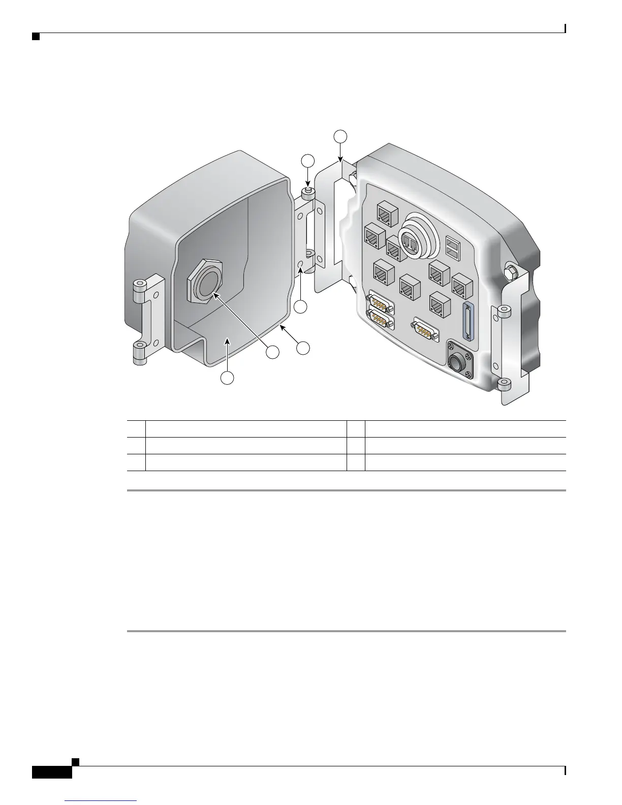
To attach the protective end cap cover to the enclosure, follow these steps (see Figure 1-10).
Figure 1-10 Protective End Cap Cover Installation
Step 1 Loosen the end cap mounting hardware (four 1/4-20 bolts), but do not remove the bolts.
Step 2 Slide the hinge brackets onto the right side and the left side of the end cap cover. The mounting tabs
should slide under the loosened bolts.
Step 3 Re-torque the two loosened bolts on the right side of the end cap cover to between 58 and 68 in-lb.
Step 4 Ensure that the gasket is fully seated in the protective end cap cover.
Step 5 Close the cover on the protective end cap cover and ensure that it is fully seated.
Step 6 Re-torque the end cap cover bolts on left side of the end cap cover to between 58 and 68 in-lb.
Step 7 Tighten the 8-32 protective cover screws (18 in-lb) until they are seated.
For sealing, we recommend Liquid Tight Connector, which is described at the following URL:
http://www.newark.com/NewarkWebCommerce/newark/en_US/mfr/brands.jsp?mfg=HUBB
1 Hinge bracket 2 Hinge point
3 Cable/service loop cavity 4 NEC pass-through
5 Gasket 6 Cap mounting
170106
1
2
3
6
4
5

 Loading...