3-4
Cisco ASA 5500 Series Hardware Installation Guide
78-17374-01
Chapter 3 ASA 5510, ASA 5520, ASA 5540, and ASA 5550
Product Overview
Table 3-1 describes the 4GE SSM LEDs.
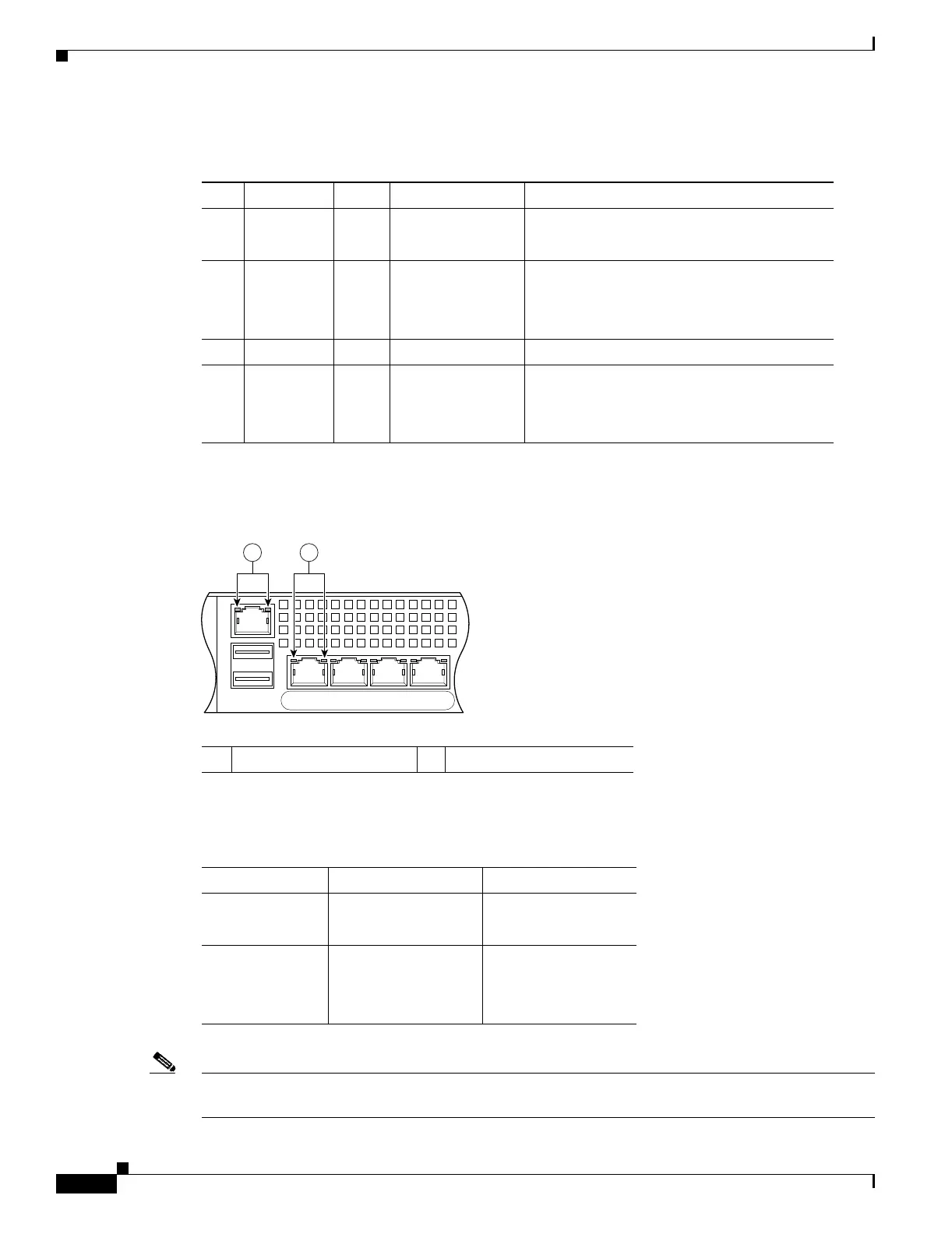
Figure 3-4 shows the adaptive security appliance rear panel LEDs.
Figure 3-4 Rear Panel Link and Speed Indicator LEDs
Table 3-2 lists the rear MGMT and Network interface LEDs.
Note The ASA 5510 adaptive security appliance supports only 10/100BaseTX. The ASA 5520 and the
ASA 5540 support 1000BaseT.
Table 3-1 4GE SSM LEDs for the ASA 5550
LED Color State Description
2, 7 LINK Green Solid
Flashing
There is an Ethernet link.
There is Ethernet activity.
3, 8 SPEED Off
Green
Amber
10 MB
100 MB
1000 MB (GigE)
There is no network activity.
There is network activity at 100 Mbps.
There is network activity at 1000 Mbps.
4 POWER Green On The system has power.
5 STATUS Green
Green
Amber
Flashing
Solid
Solid
The system is booting.
The system booted correctly.
The system diagnostics failed.
1 MGMT indicator LEDs 2 Network interface LEDs
126917
USB2
USB1
LNK SPD
3
LNK SPD
2
LNK SPD
1
LNK SPD
0
MGMT
21
Table 3-2 Link and Speed LEDs
Indicator Color Description
Left side Solid green
Green flashing
Physical link
Network activity
Right side Not lit
Green
Amber
10 Mbps
100 Mbps
1000 Mbps

 Loading...