3-15
Cisco ASA 5500 Series Hardware Installation Guide
78-17374-01
Chapter 3 ASA 5510, ASA 5520, ASA 5540, and ASA 5550
Installing the Chassis
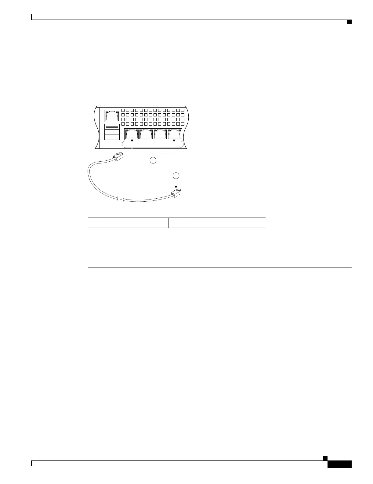
f. Ethernet ports
–
Connect the RJ-45 connector to the Ethernet port.
–
Connect the other end of the Ethernet cable to your network device, such as a router, switch or
hub.
Figure 3-16 Connecting Cables to Network Interfaces
Step 4
Connect the power cord to the security appliance and plug the other end to the power source. For
information on powering on a DC model, see the “Installing the DC Model” section on page B-8.
Step 5 Power on the chassis.
1 RJ-45 Ethernet ports 2 RJ-45 connector
USB2
USB1
LNK SPD
3
LNK SPD
2
LNK SPD
1
LNK SPD
0
MGMT
92685
2
1

 Loading...