3-28
Cisco 7200 VXR Installation and Configuration Guide
OL-5013-09
Chapter 3 Installing a Cisco 7200 VXR Router
Connecting I/O Controller, NPE-G1, or NPE-G2 Cables
Note The 1000BASE-ZX GBIC provides an optical power budget of 21.5 dB. You should measure your cable
plant with an optical loss test set to verify that the optical loss of the cable plant (including connectors
and splices) is less than or equal to 21.5 dB. The optical loss measurement must be performed with a
1550-nm light source.
Mode-Conditioning Patch Cord Description
A mode-conditioning patch cord can be used with the WS-G5486= or GBIC-LX/LH= to allow reliable
laser transmission between the single-mode laser source on the GBIC and a multimode optical fiber
cable.
When an unconditioned laser source designed for operation on single-mode optical fiber is directly
coupled to a multimode optical fiber cable, an effect known as differential mode delay (DMD) might
result in a degradation of the modal bandwidth of the optical fiber cable.
This degradation results in a decrease in the link span (the distance between a transmitter and a receiver)
that can be supported reliably. The effect of DMD can be overcome by conditioning the launch
characteristics of a laser source. A practical means of performing this conditioning is to use a device
called a mode-conditioning patch cord.
A mode-conditioning patch cord is an optical fiber cable assembly that consists of a pair of optical fibers
terminated with connector hardware. Specifically, the mode-conditioning patch cord is composed of a
single-mode optical fiber permanently coupled off-center (see Offset in
Figure 3-19) to a graded-index
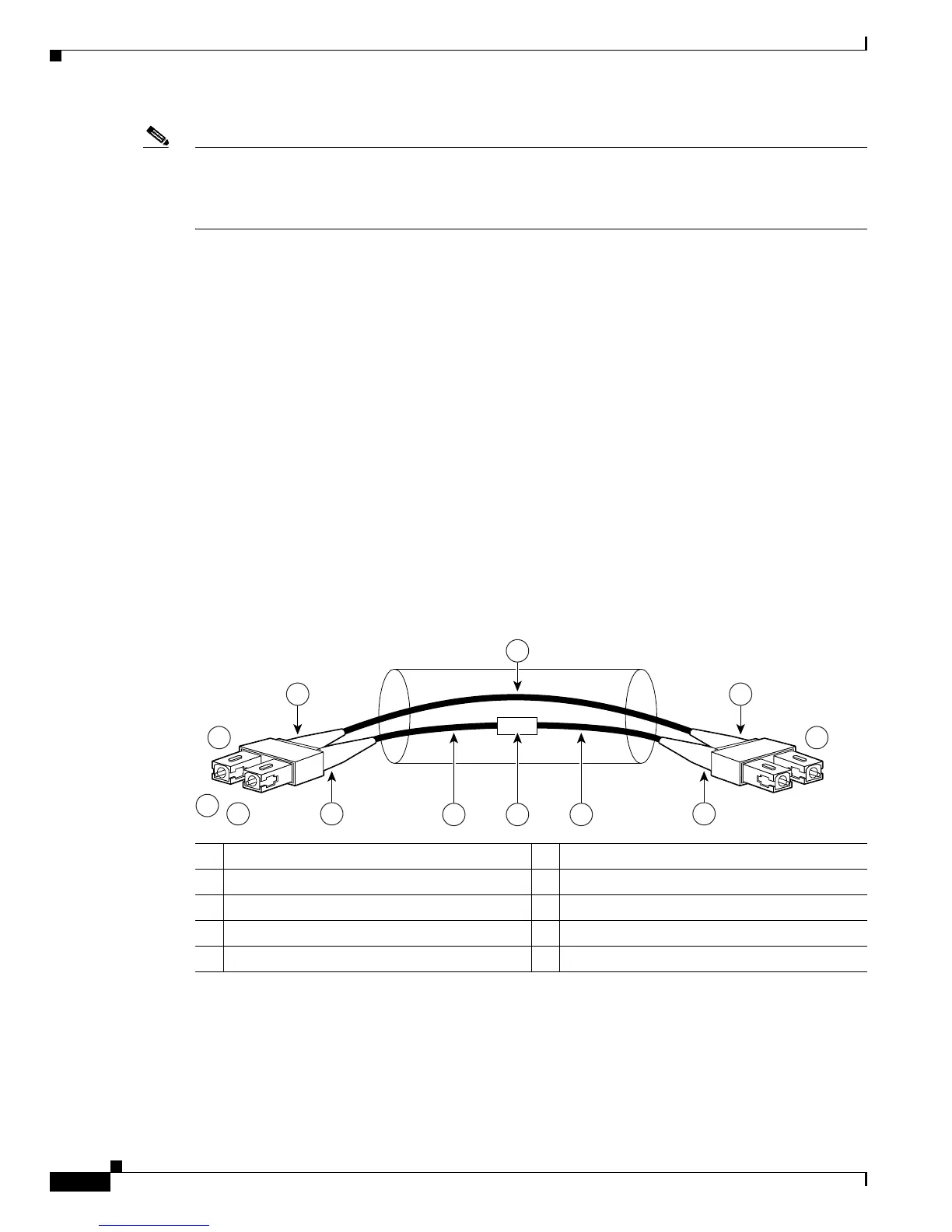
multimode optical fiber. Figure 3-19 shows a diagram of the mode-conditioning patch cord assembly.
Figure 3-19 GBIC Mode-Conditioning Patch Cord Assembly
A mode-conditioning patch cord assembly is composed of duplex optical fibers, including a
single-mode-to-multimode offset launch fiber connected to the transmitter, and a second conventional
graded-index multimode optical fiber connected to the receiver. The use of a plug-to-plug patch cord
maximizes the power budget of multimode 1000BASELX and 1000BASELH links.
1 Beige color identifier 6 Multimode fiber
2 To GE interface 7 Single-mode fiber
3 RX 8 Offset
4 TX 9 To cable plant
5 Blue color identifier