1-47
Cisco 7200 VXR Installation and Configuration Guide
OL-5013-09
Chapter 1 Cisco 7200 VXR Product Overview
Field-Replaceable Units
Note An MII LINK LED is not provided on this I/O controller because the LED is provided on external
transceivers that are required for connecting to the MII receptacle on the I/O controller. See
Chapter 3,
“Installing a Cisco 7200 VXR Router,” the “Connecting to the I/O Controller Ethernet and Fast Ethernet
Ports” section on page 3-30 for Fast Ethernet MII connection requirements.
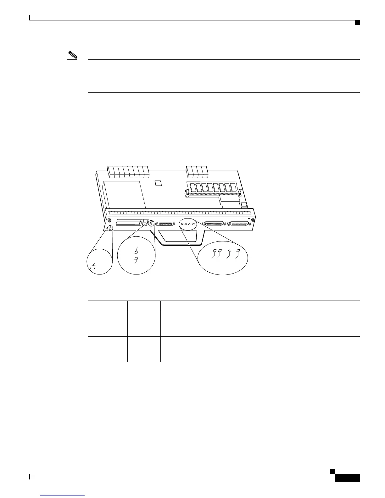
Input/Output Controller C7200-I/O-FE-MII LEDs
Figure 1-26 shows the LEDs on the I/O controller with the Fast Ethernet port equipped with a single MII
receptacle (C7200-I/O-FE-MII), and Table 1-30 lists the LEDs specific to this I/O controller model. Also
see Table 1-24 for LEDs common to all I/O controllers.
Figure 1-26 C7200-I/O-FE-MII LEDs and CPU Reset Button
Port Adapters and Service Adapters
The port adapters and service adapters installed in the Cisco 7200 VXR routers are of the same type as
those installed on the second-generation Versatile Interface Processors (VIPs) in the Cisco
7500 series
routers, in Cisco 7000 series routers with the Cisco 7000
series Route Switch Processor (RSP7000) and
Cisco 7000 series Chassis Interface (RSP7000CI), in the Cisco
AS5800 Universal Access Server, and in
the Cisco
uBR7246 universal broadband router.
Ta b l e 1-30 C7200-I/O-FE-MII I/O Controller LEDs
LED Color Function
FE ENABLE Green Indicates that the Fast Ethernet port is initialized and enabled for operation
by the system. This LED comes on after the I/O controller has been enabled
and remains on during normal operation of the router.
FE LINK Green Indicates that the Fast Ethernet port has established a valid link with the
network. This LED remains off during normal operation of the router
unless there is an incoming carrier signal.