5-2
Cisco 7600 Series Router Module Guide
OL-9392-05
Chapter 5 Multilayer Switch Module
The MSM front panel features are shown in Figure 5-1 and are described in Table 5-2.
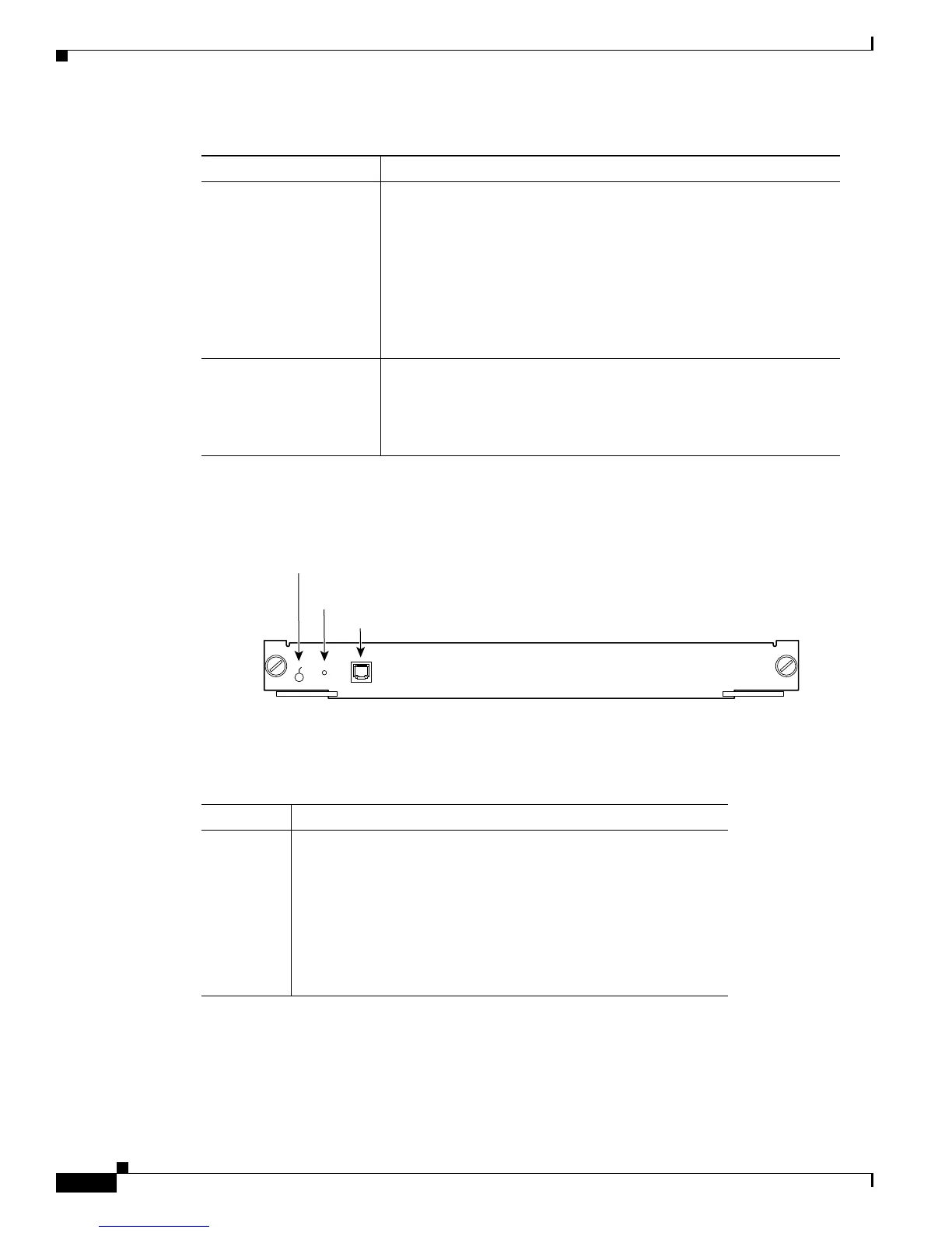
Figure 5-1 Multilayer Switch Module (WS-X6302-MSM)
The STATUS LED shows the results of the initialization and its dialog with the supervisor engine.
Table 5-2 describes the LED operation.
The CONSOLE PORT MODE switch allows you to connect a terminal to the MSM using the console
cable and adapters provided with the router. You also can connect a modem to the console port using the
cable and adapter provided with the router.
Layer 3-related protocols • IGMP v1 and v2
• IGMP snooping
• Cisco Group Multicast Protocol (CGMP) server support
• Full ICMP support
• Gateway Discovery Protocol (GDP)
• Internet Control Message Protocol (ICMP) Router Discovery
Protocol (IRDP)
Enhanced services • Integrated routing and bridging (IRB)
• Standard Domain Naming System (DNS) support
• Dynamic Host Configuration Protocol (DHCP) and Boot
Protocol (BOOTP) relay
Table 5-1 Cisco IOS Features for the Multilayer Switch Module (continued)
Feature Description
17938
MULTILAYER SWITCH MODULE
STA
TU
S
WS-X6302-MSM
CONSOLE
-PORT
MODE
Console port
CONSOLE PORT
MODE switch
STATUS LED
Ta b l e 5-2 Multilayer Switch Module STATUS LED
Color/State Description
Green All diagnostics pass; the module is operational.
Orange The module is booting or running diagnostics.
An overtemperature condition has occurred. (A minor temperature
threshold has been exceeded during environmental monitoring.)
Red A diagnostic test has failed; the module is not operational.
An overtemperature condition has occurred. (A major temperature
threshold has been exceeded during environmental monitoring.)

 Loading...


